Reverse Engineering & Scan to CAD Solution Malaysia
The part is the drawing: a worn component scanned where it sits, so its geometry can be rebuilt exactly
Quick verdict: scan to CAD is three different jobs — remaking a worn part, rebuilding a legacy part that has no drawings, or cleaning a mesh for printing. Say which one you need before the scan, because the deliverable decides how the part has to be captured.
Reverse engineering is the process of taking a physical object and rebuilding it as an editable digital model. When a component has no drawings, has worn out of tolerance, is obsolete, or needs to be improved, a 3D scanner captures its exact geometry and reverse engineering software converts that scan into CAD — a workflow known as scan to CAD. At Trinventor Solution, we supply this as a complete scanner-plus-software package, so Malaysian engineers can go from physical part to manufacturable CAD model in-house.
When do you need reverse engineering?
Obsolete or legacy parts — reproduce components for discontinued machines where the original drawings no longer exist.
Worn or damaged parts — capture a worn component, then restore its nominal geometry in CAD for re-manufacture.
Custom and aftermarket parts — build accessories, brackets and fittings that match an existing product exactly.
No CAD data — digitise physical inventory, tooling and fixtures that were never modelled.
Design improvement — capture a reference part as the starting point for optimisation or benchmarking.
The scan to CAD workflow
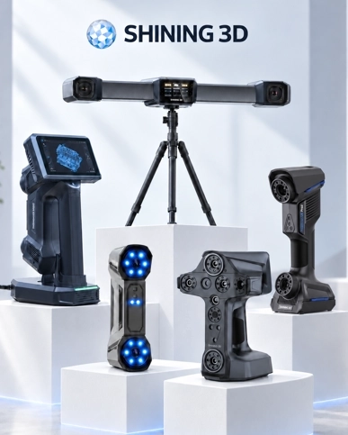
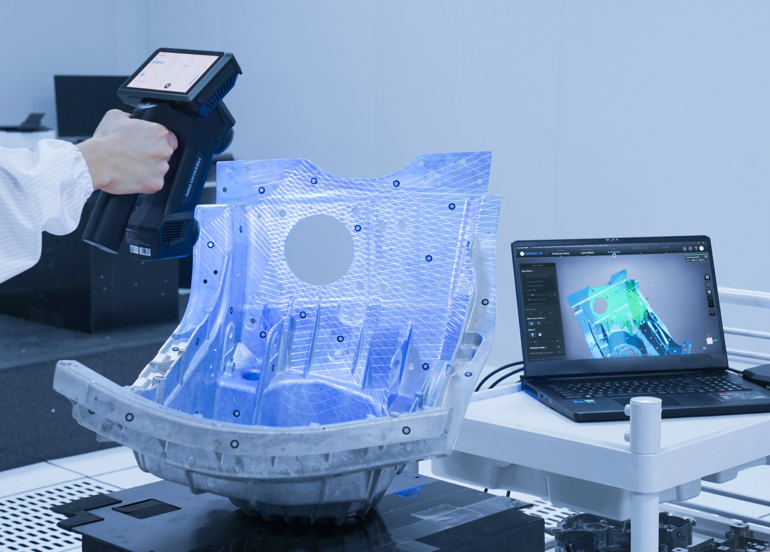
Scan the part — a Shining 3D handheld or metrology scanner captures millions of measurement points in minutes, including complex freeform surfaces.
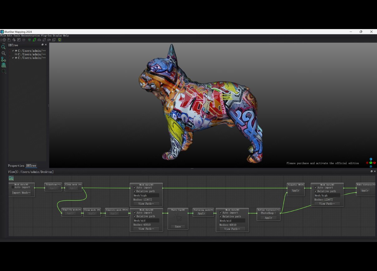
Process the mesh — align, clean and repair the scan to produce a watertight mesh.
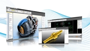
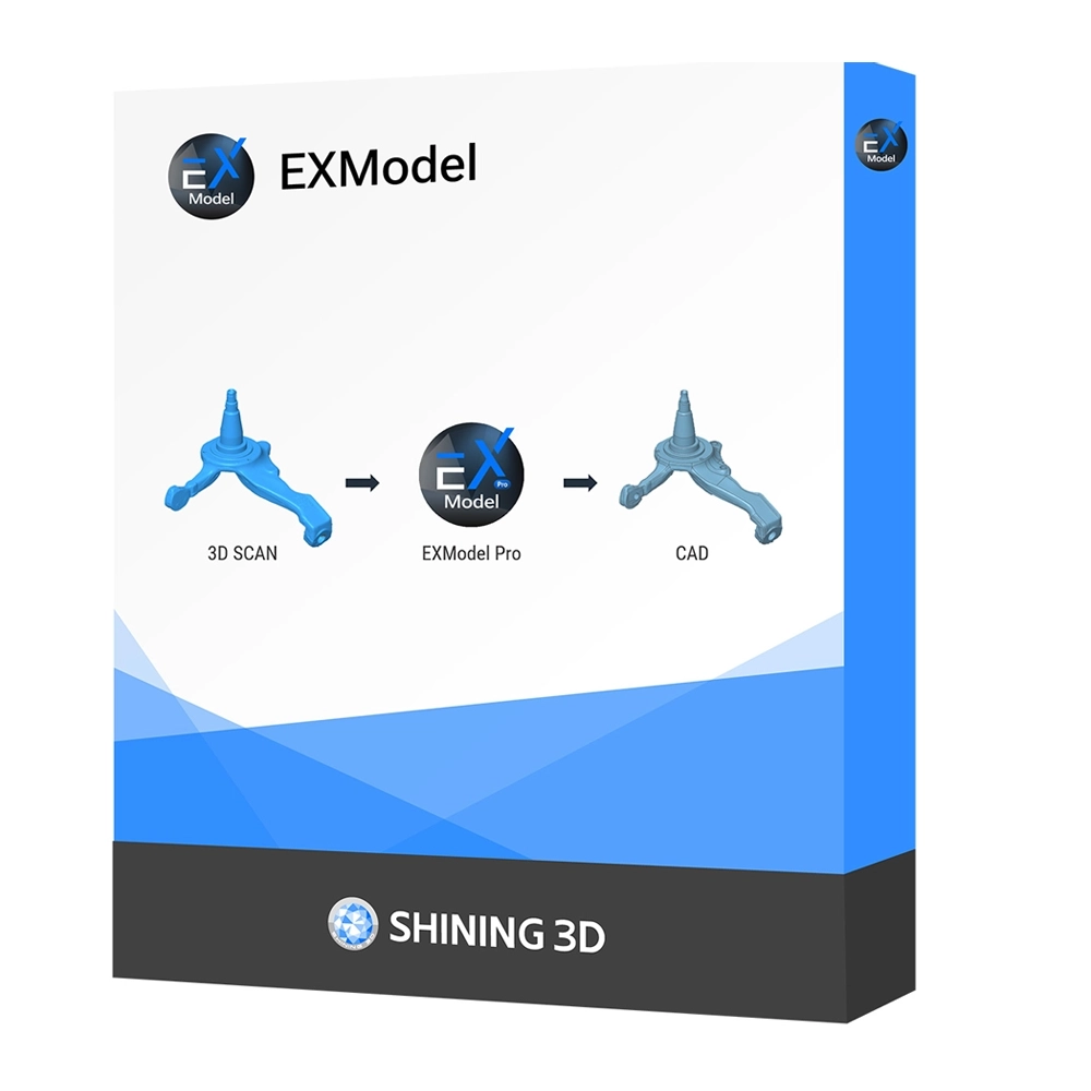
Convert to CAD — reverse engineering software such as Geomagic Design X, QUICKSURFACE or Shining 3D EXModel turns the mesh into a parametric, editable solid model with real features and sketches.
Modify or manufacture — refine the design, then output to CAM or a 3D printer for production.
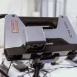
Scanning at the bench — the mesh builds as you move, and thin walls, bores and edges are captured in the same pass
Our reverse engineering solution
We sell this as a scanner-plus-software combination, not a one-off service, so you build the capability in-house:
3D scanners — Shining 3D FreeScan handheld and OptimScan automated systems for accurate geometry capture.
Reverse engineering software — Geomagic Design X and QUICKSURFACE for professional scan-to-CAD, and Shining 3D EXModel as the bridge that turns a scan mesh into a CAD solid model.
Applications across Malaysian industries
Automotive and motorsport — reproduce and modify legacy or custom components, from body panels to drivetrain parts.
Machinery and transport — maintenance, repair and overhaul (MRO) of large worn or undocumented parts for rail, marine and construction equipment.
Energy and heavy industry — rebuild mining, oil & gas and power-generation components without original drawings.
Electronics — reverse engineer housings, connectors and enclosures for repair or redesign.
Medical and dental — create accurate anatomical models, orthotics, prosthetics and custom devices.
Education and research — teach design and manufacturing principles with real scanned geometry.
Why scan to CAD instead of manual measurement?
Traditional measurement with calipers, CMM probing or manual modelling can take days on a complex freeform part and still miss detail between measured points. A 3D scanner captures the entire surface at once, so the resulting CAD model reproduces complex curves and organic shapes that are nearly impossible to measure by hand. For engineering and manufacturing work, that means faster turnaround and a more faithful digital twin of the physical part.
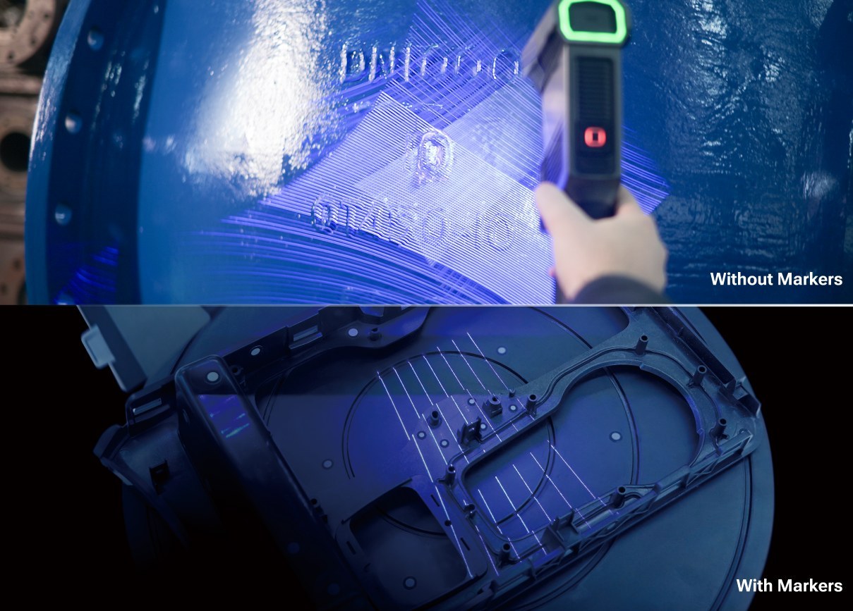
What the scan has to capture: a complete, closed mesh — holes, thin features and internal geometry included
Which scanner for scan-to-CAD work
What you are doing
Machine
Why it fits
Obsolete, broken or undrawn parts — rebuild the design
Tri-mode professional handheld, 19 + 19 crossed blue laser lines and IR VCSEL; handles machined, dark and glossy surfaces without spray and produces clean CAD-ready data
0.02 mm metrology handhelds with built-in photogrammetry; the UE Nova reaches a 2600 × 2200 mm field of view for objects that would otherwise need repositioning
Reverse engineering fails on the drawing board more often than at the scanner, because something the designer needed was never captured. Before the scan, agree what the model has to reproduce:
Datums and fit surfaces first — where the part bolts to something else decides everything downstream.
Bores, threads and sharp edges — optical scanning rounds a sharp edge and cannot see into a deep bore. This is exactly the case where a tracked system with a contact probe, such as the FreeScan Trak Pro2, earns its place: the same session scans the surface and probes the holes. See the method comparison.
Symmetry and pattern — one good quadrant plus a note about the pattern beats scanning the whole part at high detail.
The reference frame — on large parts, photogrammetry or a tracker keeps the drift out before CAD work begins.
Gaps and missed areas show up during capture, not after — which is what keeps a rebuild honest
Where the tolerance comes from
The model is only as trustworthy as the data under it. A metrology handheld holds 0.02 mm with ISO 10360 acceptance testing; a tracked system holds 0.023 mm across a 9.6 m³ volume; a fixed optical system such as the OptimScan Q12 goes finer again at 0.005 mm class. What those numbers mean, and how volumetric accuracy differs from a resolution figure, is set out in accuracy explained — worth ten minutes before you specify a tolerance you cannot prove.
Where the tolerance comes from: the scanner and the reconstruction strategy are chosen around the fits that matter
Frequently asked questions
When is reverse engineering cheaper than remaking from drawings?
When the drawings do not exist or no longer match the part. An obsolete machine part, a casting with no CAD, a component that has worn out of tolerance — scanning captures what is actually there, and software turns that into an editable model. The alternative is measuring by hand and rebuilding the design from measurements, which is slower and introduces interpretation at every step.
What accuracy can scan-to-CAD hold?
The scan is as good as the scanner, and the CAD is as good as the software and the operator. A metrology handheld such as the FreeScan Combo+ Wireless holds 0.02 mm with ISO 10360 acceptance testing; the professional EinScan Rigil holds volumetric accuracy up to 0.04 + 0.06 mm/m. For organic and freeform parts, that is far better than the manufacturing tolerance of the replacement you are making.
Can you reverse engineer a part without any CAD software of our own?
Yes — that is the service route. Send us the part and we return the mesh, the CAD-ready surface, or a full parametric model depending on what you asked for. Many customers start that way, see the output quality, and then decide whether to bring the workflow in-house.
What do I actually receive at the end?
At minimum a mesh (STL, OBJ or PLY). For engineering use, a CAD-ready surface in STEP or IGES. Where the geometry calls for it, a parametric model that can be edited rather than just measured. Tell us what happens next — machining, printing, moulding — and it decides which output is right.
Which scanner do you recommend for reverse engineering in Malaysia?
The EinScan Rigil for general professional work and the FreeScan metrology handhelds where the output has to be proved — and we will scan your part during a demonstration so the decision is made on your geometry, not a brochure.
Can you convert a scan into a STEP file?
Yes — that is the point of scan to CAD. The surfaces are fitted and stitched into a solid model you can machine, with a STEP or native CAD file as the deliverable. What arrives in each case is set out under what you receive.
What does a reverse engineering job cost?
Quoted per part, because the work is in the modelling rather than the scanning. The drivers are how much of the shape is free-form, the tolerance you need held, and whether you want a manufacturing-ready solid or a comparison report. See scanning service pricing for how those jobs are scoped.
Talk to our team
Tell us your project and we will match a scanner and software combination to your budget, materials and accuracy requirement. Contact Trinventor Solution for a live demo, consultation and local after-sales support in Malaysia.