3D Scanner Accuracy Explained: Resolution, Accuracy and Volumetric Accuracy
3D Scanner Accuracy Explained: Resolution, Accuracy and Volumetric Accuracy
Quick verdict: Three numbers decide whether a 3D scanner can do your job, and they are not interchangeable. Resolution is the smallest feature it can see. Accuracy is how close a point lands to the truth. Volumetric accuracy is how much error accumulates over a large object — and it is the number most data sheets quietly avoid. Buy for the third if your parts are bigger than your hand.
Ask a supplier for the accuracy of a 3D scanner and you will usually get one figure, quoted with confidence, followed by the words “up to”. Ask a metrologist and you will get a conversation about artefacts, standards, working distance and the difference between a single point and a part two metres long.
This is the plain-language version: what each number means, how accuracy claims are produced, what actually erodes accuracy in a real workshop, and how to specify the accuracy you need so a supplier cannot sell you the wrong machine.
The three numbers
Term
What it means
Typical range on our scanners
Resolution / point spacing
The smallest detail that appears in the data — how close together the measured points are, and how small a feature the scanner can see
Fine enough for engraving, chamfers and small radii on structured light; coarser on fast handheld scans
Accuracy (single field of view)
How close one measured point is to its true position, under good conditions
0.005 mm on the OptimScan 5M Plus; 0.01 mm on AutoScan Inspec2; 0.02 mm class on FreeScan handhelds; 0.05 mm on texture-focused machines
Volumetric accuracy
How much error accumulates across a volume — the number that matters on large or long parts
Quoted per metre by metrology vendors; where photogrammetry, VPG or an optical tracker earns its price
A scanner can be excellent on the first two and mediocre on the third. That is the classic failure mode in industry: a machine that measures a 100 mm reference artefact beautifully, then drifts noticeably over a two-metre component because it has no global reference to anchor itself to.
Rule of thumb: the scanner must be roughly four times more accurate than the tolerance you are checking. If the drawing says ±0.1 mm, a 0.025 mm scanner is a reasonable instrument choice — and a 0.005 mm machine is money spent on capability your process cannot use.
How accuracy claims are actually produced
Reputable manufacturers measure against a calibrated artefact — typically a set of spheres or a step gauge whose true dimensions are known and traceable. The scanner measures it in a controlled environment, at a specified working distance, and the difference between measured and true is reported. Two details in that sentence are where reality lives: controlled environment and specified working distance.
Standards worth knowing by name:
VDI/VDE 2634 — the German guideline for optical 3D measuring systems, split by measuring principle (Part 2 for area-based/structured light, Part 3 for multiple-view systems). It defines how probe-form error and sphere-spacing error are tested, so it is the fairest comparison between machines.
ISO 10360 — acceptance and reverification testing for coordinate measuring systems, including optical ones. When a machine is described as “ISO 10360-certified”, this is what it means.
ISO 17025 — accreditation of the laboratory, not the scanner. A tracked measuring system operating inside an accredited workflow can produce results a customer’s auditor will accept.
PTB certification — certification of a module by Germany’s national metrology institute. Some inspection modules, such as the one in the FreeScan Omni, carry it.
If a supplier cannot say which of these their accuracy figure is tied to, treat the number as marketing.
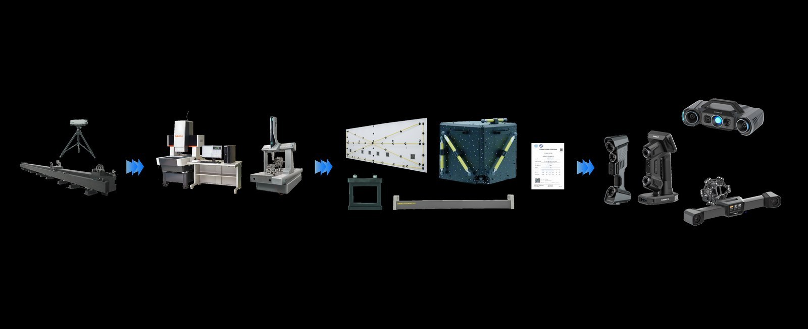
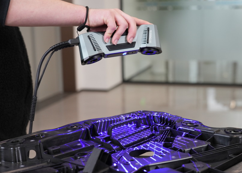
How a manufacturer proves its numbers: an accuracy-validation process tied to recognised metrology standards, rather than one quoted figure.Operator technique is the biggest variable in handheld work: steady passes, full coverage, no stretching one setup
What erodes accuracy in a real workshop
The scanner specification does not change when you take it out of the showroom. Everything around it does.
Factor
Effect
What to do
Reference and tracking strategy
Without a global reference, small errors accumulate over distance
Use photogrammetry or VPG on large parts; markers and jump markers where features are weak; an optical tracker for the tightest work
Fixturing
A part that moves, flexes or vibrates produces clean-looking data and wrong numbers
Rigid, repeatable fixturing — and the same setup each time you remeasure
Temperature
Steel and aluminium expand roughly 10–23 µm per metre per °C. A 2 m part measured 5 °C warmer is a different size
Let parts soak in the measuring environment; record temperature on the report
Surface finish and treatment
Spray coatings and matting agents add a physical layer; shiny surfaces scatter data
Prefer spray-free scanning on finished components; verify on your own surfaces
Working distance and angle
Accuracy degrades at the edge of the field of view and at grazing angles
Scan within the manufacturer’s working range; plan extra setups rather than stretching one
Operator technique
The single biggest variable in handheld work
Train, then measure a known part weekly as a check
Calibration drift
Optics and mechanics age; accuracy claims assume a maintained machine
Keep to the calibration interval and keep the certificates
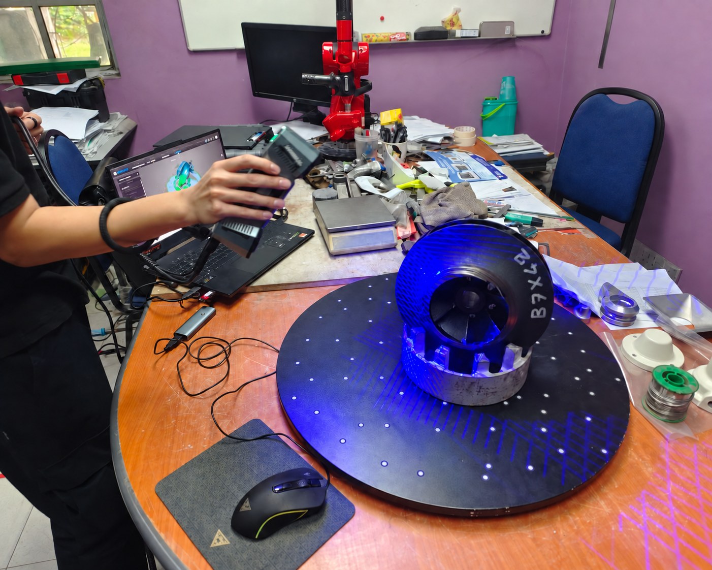
A real workshop bench, not a calibration lab: the part sits on a rotary table, the surface reflects and the tools are within reach. Most of the error in a real job comes from here, not from the scanner.
Resolution is not accuracy
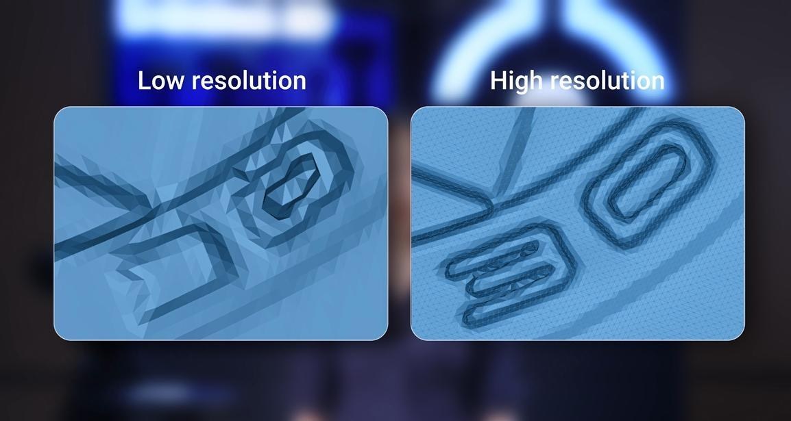
A high-resolution scanner with poor accuracy gives you a beautifully detailed wrong model. A lower-resolution scanner with good accuracy gives you a coarse but reliable one. For inspection, accuracy first, resolution second. For reverse engineering and small-detail capture, both matter — which is why a structured light system at 0.005–0.01 mm (OptimScan Q12, AutoScan Inspec2) is the tool for small, intricate parts, while a handheld laser (FreeScan Combo+ Wireless, FreeScan UE Pro2) wins on larger objects and awkward surfaces.
Same part, two resolutions: the detail you can see is not the same thing as the accuracy you can trust.
How accuracy is quoted — and how to read it
“Up to” means best case in ideal conditions. Ask what the typical figure is on a real part.
Per metre vs per field of view — a 0.02 mm figure on a single view and a 0.02 mm + 0.015 mm/m figure across a volume are different promises. The second is the honest industrial form.
With markers is a condition, not a footnote. Some machines quote their best number only in marker mode.
Repeatability is often more useful to a buyer than absolute accuracy: scan the same untouched part twice and compare the reports.
Specifying what you need
Write this down before you talk to any supplier, because it turns a sales conversation into an engineering one:
The tightest tolerance you must measure on a drawing, and the feature it belongs to.
The largest distance across your biggest part.
The surfaces involved — and whether you are prepared to treat them.
The output your customer expects: a mesh, a CAD model, or a report with tolerances on it.
The environment: bench, shop floor, outdoors, or an installed machine you cannot move.
Who runs it, and how often.
Those six answers determine the accuracy class you need, and the accuracy class determines the family. Anything you cannot justify from that list is capability you are paying for but not using.
Verifying before you buy
Ask any supplier to do this, and if they refuse, walk away:
Scan a part you already know the dimensions of, and show the deviation report.
Scan it twice, untouched, and show both reports side by side.
Scan the largest representative part, not the friendliest one.
State the alignment method used in the report — the same mesh aligned two ways gives two different answers.
Provide the calibration certificate and say what it is traceable to.
We run this protocol in our own demos, and we publish the standards our machines sit behind rather than a single unqualified number. See the buyer’s guide for how the tiers map to tolerances.
When accuracy quietly stops being the problem
Plenty of buyers chase the last micron when their real constraint is elsewhere: a part that cannot be fixtured, a report format their customer will not accept, a scanning setup that takes three hours, or a workflow that needs two people. Those are solved by process and training, not by buying the next machine up. The industrial scanner guide covers that side of the decision, and the quality control guide covers the workflow around it.
If you would rather not own the problem at all, our scanning service delivers inspection reports and CAD-ready files measured on metrology-grade equipment, with the machine, method and calibration reference stated on the report.
Turning your drawing tolerance into a machine choice
The three numbers above decide whether a scanner suits the job. This is the practical version: read the tightest tolerance on the drawing, halve it, and pick the tier that meets it with margin.
Your tightest tolerance
What it needs
Typical machine
0.1 mm and looser
Professional tier is comfortable; colour and speed matter more than the last micron
Not a 3D scanner — that is CMM, form tester or gauge territory
We will say so rather than quote you a machine
Tolerance questions we get asked
How do I turn my drawing tolerance into a scanner choice?
Read the tightest tolerance on the drawing and halve it — that is the rule of thumb, because you generally want the measuring instrument an order of magnitude better than the feature it judges. A 0.1 mm tolerance sits comfortably with a professional-tier scanner; 0.05 mm is metrology handheld territory; below 0.02 mm is fixed structured-light work.
What is the difference between accuracy and volumetric accuracy for my decision?
Accuracy is how close a measured point lands to the truth, usually quoted in a single field of view. Volumetric accuracy is how much error accumulates across the whole part — and it is the number that decides whether a scanner is usable on a large object. If your part is bigger than your hand, buy on the volumetric figure.
Do I need a metrology scanner for 0.05 mm work?
Not necessarily. The professional range handles many jobs at that level in the EinScan line, and the tier question is really about whether the result has to be documented and defended. If someone audits the number, you want the ISO 10360 or VDI/VDE 2634 acceptance testing that metrology systems carry.
Where do the tiers sit in practice?
Metrology — FreeScan and OptimScan: 0.02 mm handhelds and 0.005 mm fixed systems with acceptance testing. Professional — EinScan: accuracy-optimised for design and reverse engineering, volumetric accuracy up to 0.04 + 0.06 mm/m. Documentation — SHARE SLAM LiDAR: centimetre-level point clouds for buildings and plant, where the question is what is where, not how close it is to a tolerance.
What if my tolerance is tighter than any scanner you supply?
Then the honest answer is that your feature belongs on a different instrument — a CMM, a form tester or a gauge. We would rather tell you that than sell a scanner that cannot support your drawing.