EXModel Pro: Reverse Engineering Software in Malaysia
EXModel Pro: Reverse Engineering Software in Malaysia
Quick verdict: If a Shining 3D scanner is already in your workshop, EXModel is the shortest route from that scan to a CAD model. The standard tier repairs and aligns the mesh, sections the part and fits surfaces to it. EXModel Pro adds the tools that finish the job: Class A and blend surfaces, hybrid free form and parametric modelling, solid operations such as trim, cut, combine, fillet and chamfer, and a feature tree you can hand to another CAD package. Pick Pro when the model has to leave your desk and go into production tooling.
A scan is not a drawing. A scanner records a surface very well, and a mesh gives you a shape you can print, but neither tells a toolmaker where the parting line sits or tells a CAM programmer which face is the datum. Reverse engineering is the step in between: turning a physical part that already exists into a CAD model that can be edited, dimensioned, tooled and reproduced.
This article explains how that step works with Shining 3D scanners and the EXModel software family, what separates EXModel from EXModel Pro, and where the work pays for itself in a Malaysian workshop.
What scan to CAD means, and why a mesh is not a CAD model
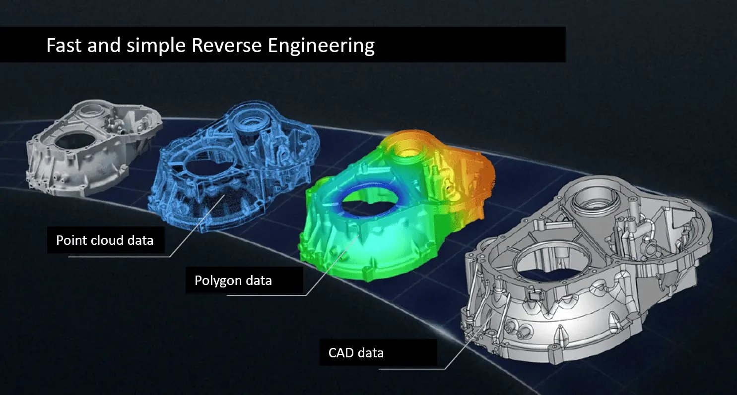
A scan arrives as a point cloud. Scanning software turns that into a mesh: a thin skin of small triangles wrapped around the surface. It is a faithful record and a poor design document. Nothing in a mesh is named, dimensioned or editable. There is no cylinder, no axis, no hole diameter, no fillet radius and no tangent condition. If a bore has to come out slightly larger, there is no bore to change, only triangles to push around.
A CAD model is built from exact geometry instead. Planes are defined as planes, cylinders carry an axis and a diameter, and the model keeps a tree of features recording how each one was made. That tree is what allows somebody else to open the file next year, change one dimension and regenerate everything that depends on it.
Scan to CAD software sits between the two. It takes the mesh, lets you repair and align it, lets you slice it into sections, and then rebuilds exact geometry on top: primitives for the regular features, fitted or swept surfaces for the free form ones, and a closed solid body that a CAD or CAM package will read as a solid rather than as loose surfaces to be stitched together.
The distinction is practical. A mesh is fine as the final product if the goal is a 3D printed replica or a colour deviation report. It stops being fine the moment someone has to machine the part, mould it or change it. Machining a mesh means working with faceted geometry where CAM cannot reliably find a true flat, and mould design needs clean, mathematically defined surfaces before draft and shrinkage can be applied.
The scanner captures the geometry; the software that follows is what turns that capture into something a CAD package will open
The scanning half: which Shining 3D scanners connect to EXModel
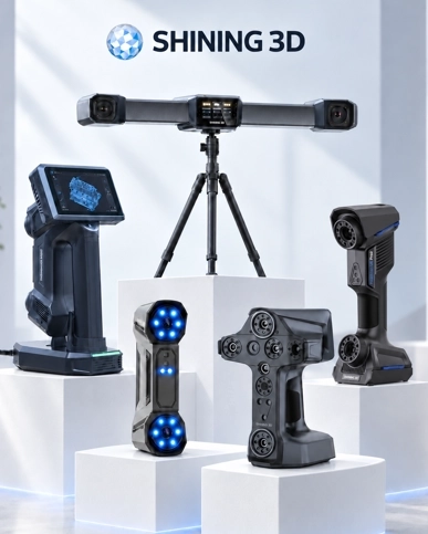
Shining 3D builds three scanner families that matter for this work: EinScan, FreeScan and EINSTAR. They capture geometry in the same basic way. Light is projected onto the part, cameras record how the pattern deforms across the surface, and software solves the shape from that deformation. What separates the models is how they track their position while you move around the part, how much punishment they take from difficult surfaces, and how large a part they can cover in one session.
EXModel works with a defined set of scanners rather than every model in the range. The handhelds we pair with it are the FreeScan Combo+ Wireless, the FreeScan Omni and the FreeScan UE Pro2. If you are buying a scanner and reverse engineering is the reason, start the conversation from that list rather than shopping the range and hoping the transfer works.
The handover itself is the part people underestimate. EXModel integrates with EXScan, Shining 3D’s scanning software, so the mesh you have just captured transfers across in one click. No export to a file, no hunting through folders, no re-import with the wrong units. Scanning and rebuilding happen in the same working session, which matters when you are scanning a part that has to go back on a machine the same afternoon.
Two things decide how well the scan comes out before software is involved. The first is surface finish. Matt, light coloured parts scan easily; polished, black or translucent parts fight you, and a light dusting of scanning spray settles the argument at the cost of a thin coating that shows up in the data. The second is tracking: the scanner needs markers or distinctive features to hold its position, so awkward or repetitive shapes take longer to cover reliably.
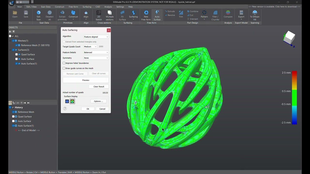
Auto surfacing fits a quad surface over the scanned mesh, which is the step that turns measurement data into usable geometry
What EXModel actually does with your scan
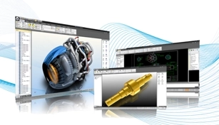
EXModel is Shining 3D’s own scan-to-CAD reverse engineering software, and its job is narrow and specific: take a scanned mesh and produce a CAD solid model. What comes out are proper solids, with exact surfaces and closed volumes, rather than polygon soup with a misleading file extension, which is why the exports behave themselves further downstream.
The tools it gives you fall into recognisable groups, and the same groups appear in both tiers:
Mesh editing: filling holes left by occluded or reflective areas, smoothing scanner noise, and editing mesh boundaries where the scan ran out of part.
Mesh alignment: positioning parts by coordinates, by N-points, or by a fine alignment that brings several scans into one coordinate system.
Primitives extraction and construct references: pulling cylinders, planes and cones out of the scan and using them to build a reference frame for the rest of the model.
Cross sections, 2D sketching and 3D sketching: cutting the part into slices you can measure and sketch over.
Fit, manual free form modelling and auto surfacing: rebuilding curved geometry, either by automatic surface fitting or by hand where the surface matters.
Extrude and revolved surfaces: generating geometry from sketches for the round and straight portions of a part.
Export features and profiles as IGES, STEP or DXF: the neutral formats that carry the result into the next system.
None of this is automatic, and it is not meant to be. Auto surfacing gives you a usable body quickly on parts with straightforward curvature. Where a surface has to be right, you fit it by hand and check it against the mesh. Judging when to accept a fit and when to redo it is where the skill in scan to CAD sits.
EXModel vs EXModel Pro: the full feature comparison
Both tiers share the same foundation. The table below is the official feature split from Shining 3D. Read it carefully before deciding that the upgrade is optional.
Feature
EXModel (standard)
EXModel Pro
Mesh editing: fill holes, smoothing, edit boundaries
Yes
Yes
Mesh alignment: coordinates, N-points, fine align
Yes
Yes
Primitives extraction and construct references
Yes
Yes
Cross sections, 2D sketching, 3D sketching
Yes
Yes
Fit, manual free form modelling, auto surfacing
Yes
Yes
Export features and profiles as IGES, STEP, DXF
Yes
Yes
Extrude and revolved surfaces
Yes
Yes
Helix, loft, sweep, fill surface (Class A), blend surface, flatten
No
Yes
Constraints, offset and patterns in 2D sketch
No
Yes
Sketch assist in 2D sketch
No
Yes
Unroll mesh and roll 2D sketch
No
Yes
Trim to solid, cut, combine, intersect, fillet, chamfer, patterns
No
Yes
Hybrid modelling (free form and parametric)
No
Yes
Transfer design and feature tree to other packages
No
Yes
Read the bottom half of that table as the difference between a model that describes a shape and a model that can be worked on. The top half is reconstruction: repair the mesh, line it up, slice it, fit surfaces and send something out. The bottom half is modelling, in the ordinary engineering sense of the word.
Which tier does your work actually need?
The standard tier suits jobs where the CAD model is a starting point you intend to redraw anyway, or where surfaces and sections carry the whole story. A worn shaft, a bracket, a simple housing, a replacement cover: repair the mesh, align it, section it, fit the surfaces, export the STEP and let your CAD team take over. On that kind of part the tools in Pro would sit unused.
Pro starts earning its place when the geometry is not simple or when the file has to stand on its own:
Curvature that has to flow. Fill surface, blend surface and Class A surfacing are what separate a lumpy reproduction from a surface another engineer would accept. Handles, enclosures, covers and anything moulded with a visible face fall into this group.
Solid operations. Trimming to a solid, cutting, combining, intersecting, fillets, chamfers and patterns let you complete the model rather than hand over surfaces and hope.
Hybrid modelling. Most real reverse engineering jobs start as free form reconstruction and end as a parametric part. Hybrid modelling lets both live in the same file.
Helix, loft, sweep and flatten. Threads, impeller-style blades, ducting and formed sheet parts need these. Unrolling a mesh and rolling a 2D sketch back onto it is the tool for anything that started life as flat sheet.
Handover. If the model has to go to a toolmaker, a customer or a design office with a feature tree they can edit rather than a dead solid, that transfer capability decides the tier on its own.
The second argument for Pro is quieter. It changes the work you can accept. A workshop that can only reproduce simple parts turns away the interesting jobs; one that can rebuild a moulded cover with Class A surfaces and hand over an editable feature tree can quote for them.
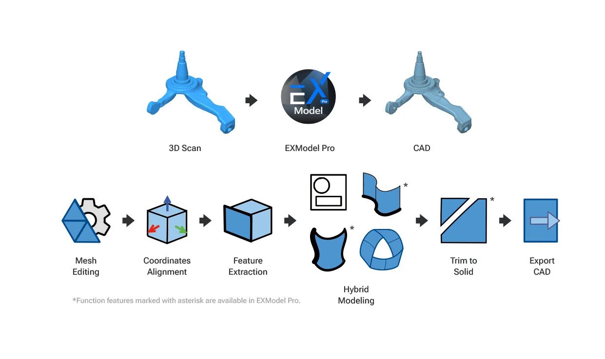
The workflow runs mesh editing, alignment, feature extraction and hybrid modelling, then trims to a solid and exports to CAD
The reverse engineering workflow, step by step
The sequence below is the one that causes the least rework. Skipping ahead to surface fitting before the mesh is clean is the most common way to lose a day.
Prepare the part. Clean it. Oil, rust and loose paint are not part geometry. Dark, shiny or transparent areas get a light coating of scanning spray, and you note that the coating adds a thin layer if you are working to tight tolerances.
Plan the scan. Markers or natural features for tracking, the part fixed so it cannot move mid-session, and coverage that includes the datums you care about rather than only the interesting face.
Scan and capture. Multiple passes are normal. Scan from several angles so occluded pockets and deep recesses get captured from a different direction, and keep the scan data as your reference for later verification.
Transfer to EXModel. One click from EXScan. The mesh lands in the same session, in the coordinate system you scanned it in.
Clean the mesh. Delete stray islands, fill holes, smooth scanner noise. Everything you do here propagates into the surface fitting later, so this is not housekeeping.
Align and merge. Bring the individual scans into one coordinate system by coordinates, by N-points or with a fine alignment, then merge them into a single mesh.
Build a reference frame. Extract primitives, set the planes and axes the part will be modelled against, and check that the alignment matches how the part actually sits and functions.
Section and sketch. Take cross sections through the part, sketch over them in 2D, and use 3D sketches where the geometry runs along the surface.
Reconstruct the surfaces. Extrude and revolve the regular features, auto surface the straightforward curvature, and fit or model the free form areas by hand. In Pro, this is where loft, sweep, helix, Class A and blend surfaces do their work.
Convert to a solid. In Pro, trim to solid, combine, cut, intersect, fillet, chamfer and pattern until you have one closed body. In standard, you finish the reconstruction and take surfaces forward.
Check against the scan. Compare the model back to the mesh before you export. Small deviations are normal in reconstruction; unexplained ones mean a surface moved while you were not looking.
Export and hand over. IGES, STEP or DXF, depending on where the file is going next.
What you do with the exported IGES, STEP and DXF
The three export formats are not interchangeable, and picking the wrong one is a common source of grief at the other end.
Format
What it carries
Where it usually goes
STEP
Solid bodies, surfaces and assemblies in a modern neutral format
CAD editing, CAM toolpath, tool and mould shops, anything modern and downstream of design
IGES
Surfaces and geometry in an older neutral format, widely accepted
Older CAD and CAM systems, and shops running legacy software that reads IGES reliably
DXF
2D profiles and sketches
Laser cutting, wire EDM, waterjet, drawing overlays and section drawings
From there the paths diverge. A STEP file with a closed solid goes into CAM for toolpath and into mould design for cavity, core and parting work. A DXF profile goes straight to a cutting machine or into a shop floor drawing. The model also feeds a printer or CNC machine for a replacement part, and a programmed inspection routine that measures the next batch against what you just built. That closes the loop: scan, rebuild, make, then scan the result to prove it matches.
Moulds and tooling: where reverse engineering usually starts
Tooling is the strongest case for scan to CAD in Malaysia, because tooling is where a missing file hurts most. A mould insert, a die, a jig or a forming tool that has been running for years often exists only as steel. The original drawing may have gone with the engineer who left, or the tool was made by a supplier who never handed over the model in the first place.
Scanning gives you the shape. Building it into a solid model gives you something you can work with. Once the cavity and core are reconstructed as exact geometry, the operations that actually get the job done become possible: separating the part from the tool body, defining the parting line, applying the material shrinkage your process needs, adding draft to faces that need it and preparing the tool for a duplicate. Without a model, none of that can be done on a computer.
Repair work follows a similar path. A damaged die or worn mould can be scanned, compared against the model of the tool as it should be, then built up by welding and remachined to the original geometry. The comparison shows where the wear sits and how much stock you have before you touch the tool. Duplicating a proven tool for a second production cell is the same exercise again, with the reverse engineered model as the master.
Obsolete spares and legacy machines
The second money maker is the spare part nobody sells any more. A production line stops because a housing, a gear blank, a roller, a chute or a coupling has failed, and the machine it belongs to was imported years ago. The supplier has changed the design, the part has a long lead time, or the machine model is out of support entirely. The part in your hand is the only record of its geometry.
Reverse engineering changes the nature of that problem. Instead of hunting for a spare, you create the model, and from the model you can machine or print a replacement, then keep the file. The next failure costs you a setup rather than a search. Parts that were repaired by hand in the past, with material added and filed back to fit, become repeatable. That is the real return: not one replacement part, but a part that can be made again whenever it is needed.
The same logic applies to jigs and fixtures built on the shop floor. Scan a fixture that works, model it, and the second and third copies come out to the same geometry rather than to whoever measures it next.
Quality inspection of worn parts
Not every scan needs to become a model. Sometimes the question is not what shape the part is, but how far it has moved away from the shape it should be. That is inspection, and it uses the same scanners and the same scan data as reverse engineering, which is why the two are often bought together.
For wear work, the scan is compared against a CAD model or against a scan of a known good part, and the deviation is reported across the surface. Rollers, blades, gear teeth, sealing faces and guideways all answer useful questions that way: how much material has gone, where contact is actually happening, whether a component is bending under load rather than wearing evenly. Wall thickness checks on castings and moulded parts do the same job from another direction, comparing inner and outer surfaces.
The value is in the decisions it settles. A batch can be released or held on measurement rather than opinion, a worn component judged against a limit instead of a feeling, a supplier dispute settled with a report. Reverse engineering and inspection are two halves of one capability, and a workshop with a metrology-grade 3D scanner can move between them without buying the same data twice.
What to check before you commit
The software decision is downstream of a handful of practical questions. Work through them before a trial starts and you will spend the trial usefully.
Does your scanner connect? Confirm your model is one of the handhelds we pair with EXModel: FreeScan Combo+ Wireless, FreeScan Omni or FreeScan UE Pro2. If you do not own a scanner yet, choose with the transfer in mind.
Are you modelling, or only reconstructing? If the deliverable is a simple part going into your own CAD system, standard EXModel covers it. If surfaces have to be Class A, if the model needs fillets and boolean operations, or if a feature tree has to be handed over, plan for Pro from the start.
Use the trial on real work. Shining 3D offers 30 days on standard EXModel and 15 days on EXModel Pro. Do not spend either on a test block. Pick the part that has been sitting on the shelf because nobody can model it, and see the workflow through to an export.
Test the export, not just the model. Open the STEP file in the CAD or CAM system your team actually uses, and check that it arrives as a solid at the right scale. This takes ten minutes and prevents an unpleasant surprise later.
Check who will do the work. Scan to CAD rewards a person who understands both the part and the process. Budget time for training whoever owns it, because the software is a tool and not a replacement for that judgement.
Keep the mesh alongside the model. The scan is your evidence and your reference for the next comparison. Store it with the CAD file.
Frequently asked questions
Does EXModel replace my CAD software? No. It rebuilds geometry from a physical part and hands the result on as IGES, STEP or DXF. It complements your existing CAD, and with EXModel Pro the design and feature tree can transfer to other packages so your CAD team can keep working parametrically.
Which scanners work with EXModel? The FreeScan Combo+ Wireless, the FreeScan Omni and the FreeScan UE Pro2 — the metrology-grade handhelds we pair with EXModel for scan-to-CAD work — and the mesh transfers from EXScan in one click.
What is the difference between the two trials? Standard EXModel runs for 30 days and EXModel Pro runs for 15 days. If you are deciding between tiers, run the standard trial first on a simple part, then use the shorter Pro trial on the job that genuinely needs Class A surfaces or solid operations.
How accurate is a reverse engineered model? It depends on the scan and on the surfaces you fit. A part that is scanned cleanly, fitted carefully and checked against the mesh will reproduce the original closely, which is why the check before export matters. If in doubt, scan the finished part again and compare it with your model.
Can the exported model go straight to machining? Yes, in STEP or IGES. A closed solid model is what CAM needs to generate toolpath, and DXF profiles cover the 2D operations such as laser cutting, wire EDM and waterjet. Whether it goes straight to the machine or through a CAD review first is your call, but the geometry leaves EXModel ready for either.