3D Scanner vs CMM: Key Differences and Best Use Cases
3D Scanner vs CMM: Key Differences and Best Use Cases
Quick verdict:a 3D scanner captures the whole surface, fast. A CMM measures selected features with the highest-confidence numbers. Choose by what you actually need to know — and if you need both, a tracked scanner with a contact probe does both in one session.
Quick definitions
What is a 3D scanner?
A 3D scanner is a measurement tool that captures the shape of an object and turns it into a point cloud or mesh. Depending on the model it projects laser lines, blue light or LED structured light, and reads the pattern back with cameras. In plain language it “sees” the outside of a part and records thousands to millions of surface points in seconds.
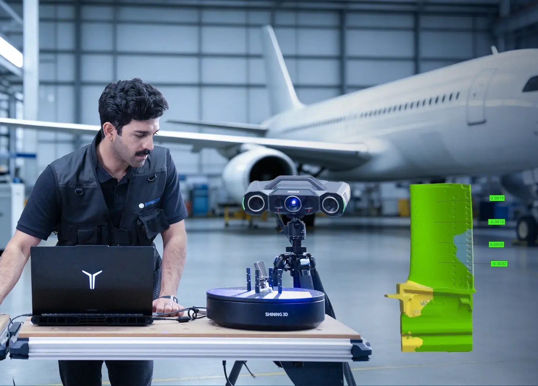
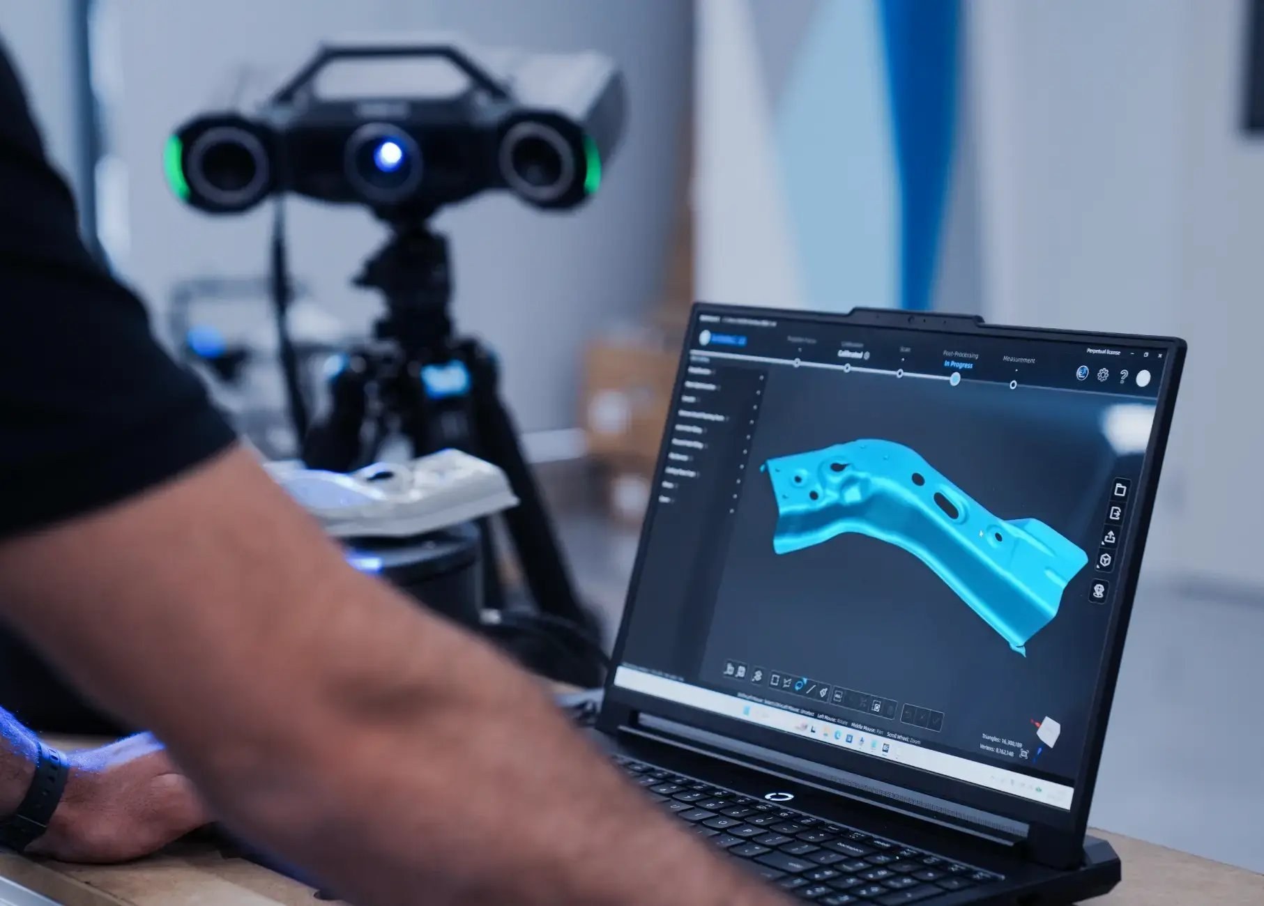
A 3D scanner records the surface — thousands to millions of points per second, in one pass.
What is a CMM?
A CMM is a coordinate measuring machine: a precision instrument that measures points in 3D space. Traditional CMMs measure by touching the part with a probe — a stylus carried on the machine’s measuring head — and some also carry optical or scanning probes. A CMM normally lives in a quality room or inspection lab, and it is the tool manufacturers reach for when they need the highest confidence, repeatable measurements and a formal dimensional report on defined features.
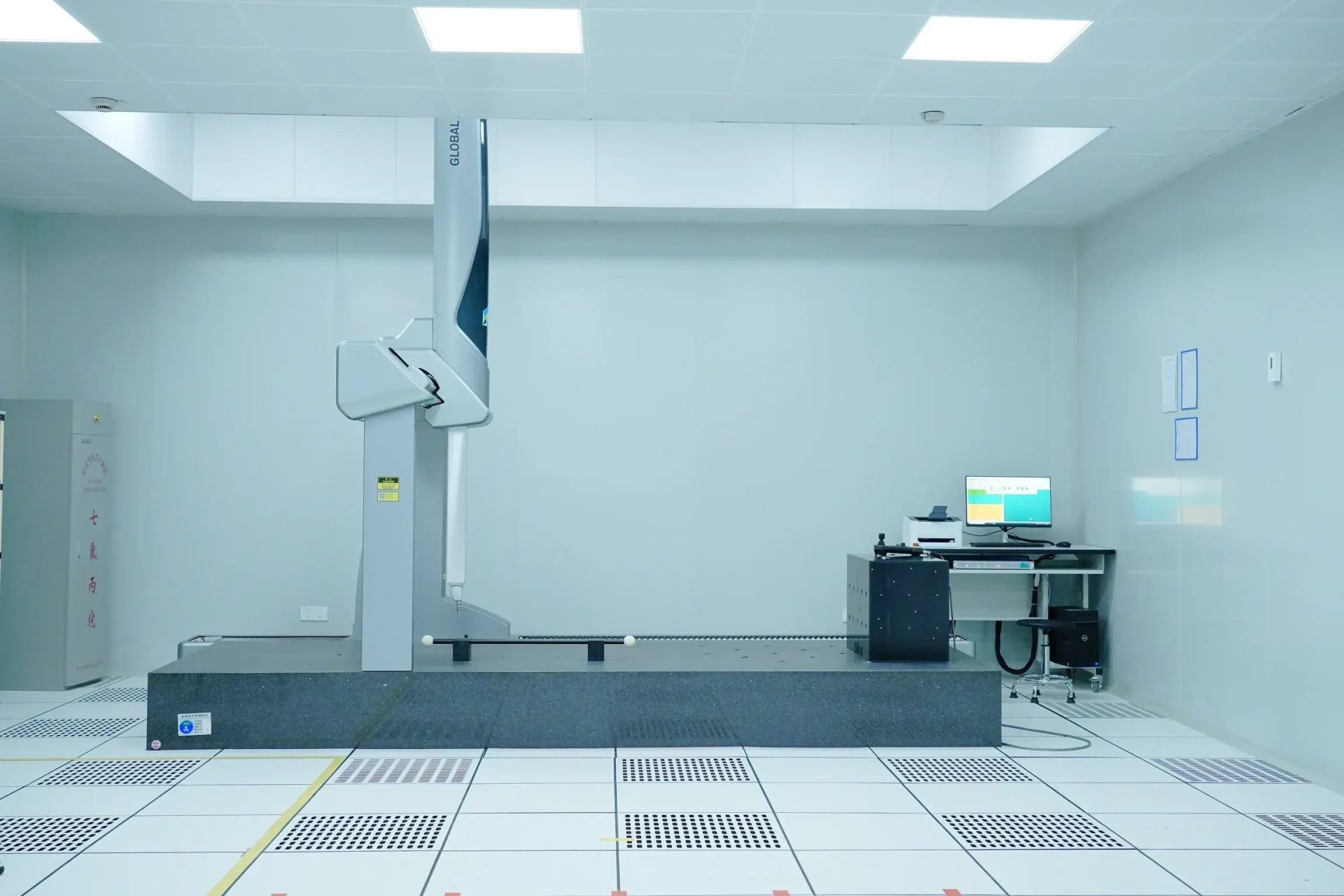
A bridge CMM in a measuring room: the reference for defined features measured to tight tolerances.
3D scanner vs CMM: the practical difference
A 3D scanner captures the full shape quickly. A CMM measures selected points very precisely. Neither is automatically better; they are designed around different strengths.
3D scanner
CMM
Measurement method
Captures surface geometry with light and cameras; collects large amounts of data at once; produces a point cloud or mesh — best for understanding overall shape and surface deviation
Measures specific points with a probe or sensor; fewer points, very tightly controlled; produces dimensional inspection reports — best for feature-based measurement and tight-tolerance validation
Speed
Faster on complex shapes and full-part inspection; large areas in minutes; no need to decide in advance which points matter
Slower on complex parts — programming, setup, fixturing and probing strategy all take time; efficient for repeat inspection of known critical dimensions
Accuracy
Depends on the scanner class, calibration, operator technique, surface finish, part size and environment. Metrology handhelds run at 0.02 mm with ISO 10360 acceptance testing; a tracked system holds 0.023 mm across a 9.6 m³ volume; fixed optical systems go finer
Quoted as a measurement uncertainty rather than a headline figure, and holds it best in a stable, temperature-controlled room with the right fixturing — the reference for tight dimensional and geometric tolerances
Portability
Handheld and easily moved — shop floor, on site, or at a customer’s premises; the answer when the part is too large, heavy or expensive to bring to a lab
Traditional bridge CMMs are stationary and need a controlled environment; portable arms and optical CMMs exist, but the best performance still comes from a stable setup
Contact probing measures the points you choose, one at a time, with well-understood uncertainty.A scanner records the full surface in one pass; a probe measures only the points you choose in advance.
Best use cases
When the 3D scanner wins
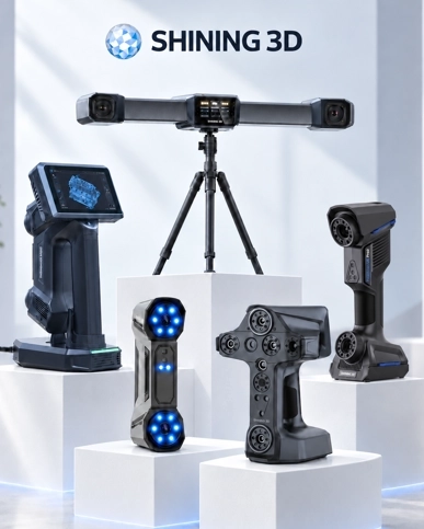
The jobs where you do not know in advance which area is wrong: mould and tool wear, first-article inspection on a complex casting, a competitor part with no drawings, a large assembly that cannot be moved onto a machine, or a surface that has to be documented as a whole. A scanner such as the FreeScan Combo+ Wireless or the FreeScan Trak Nova also gives you the data for reverse engineering and 3D printing in the same pass.
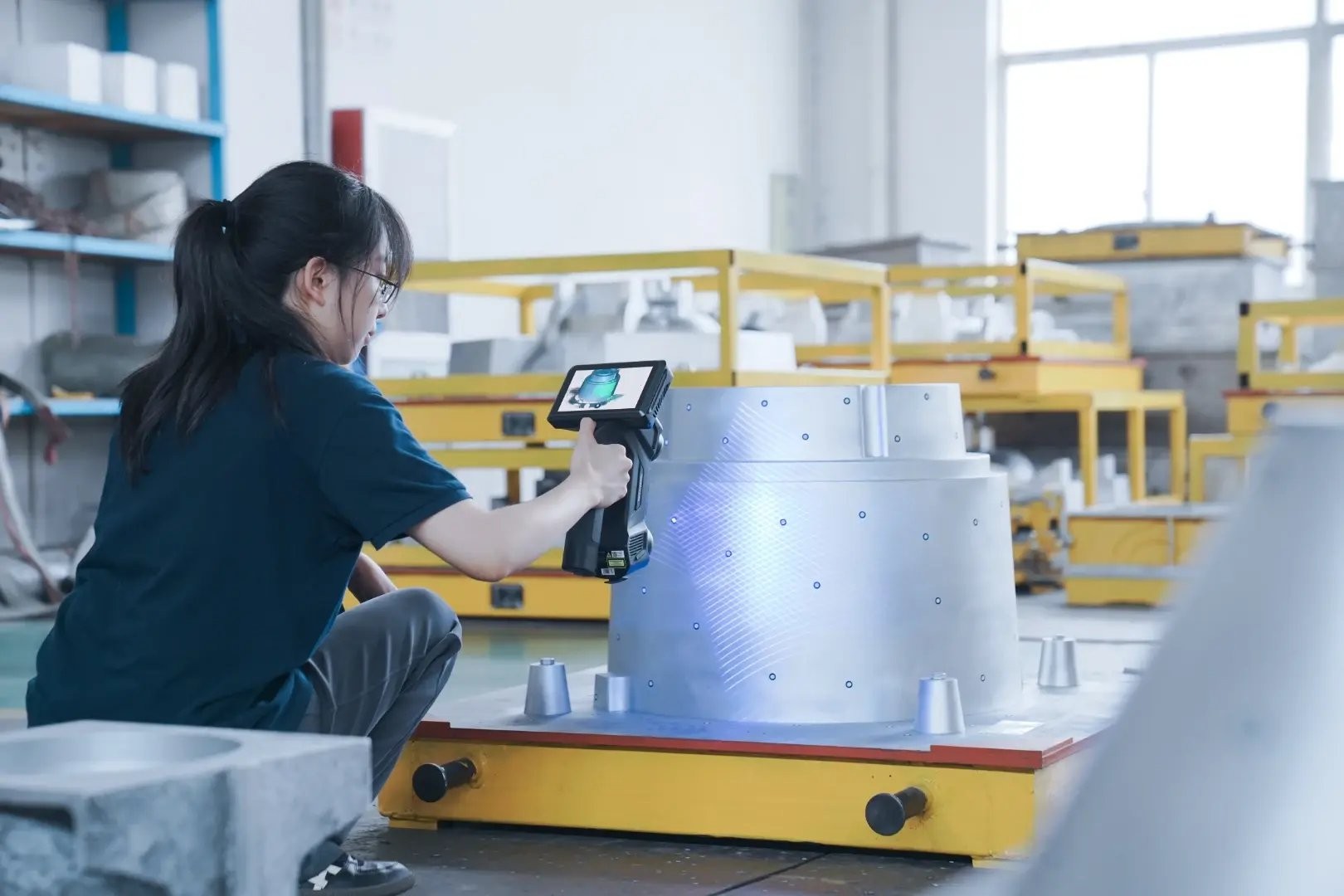
Where the part is too large to bring to a machine, the scanner goes to the part.
When the CMM is still the right tool
There is no point pretending otherwise. When a tight tolerance on a defined feature has to stand up to a customer, an auditor or an accreditation body, the probe measurement remains the reference. Deep bores, sharp edges and very small features also stay probe work. For repetitive inspection of the same critical dimensions, a CMM or an automated optical system such as the AutoScan Inspec2 is the efficient route.
When you need both
The FreeScan Trak Pro2 accepts a contact probe, so the same setup can scan the whole surface and then probe the critical features, with both sets of data in one coordinate frame and no re-fixturing. That removes the usual argument about which instrument should do which job, because a job that needs both no longer needs two setups.
What this means in Malaysia
Trinventor Solution demonstrates both routes in Kuala Lumpur or at your premises, with your own parts, so the decision is made on your geometry rather than a specification sheet. Scanners are quoted against the tolerance you have to prove — metrology handhelds, tracked systems and automated optical inspection, with local training and support. Book a demonstration or send us a part to scan.
Frequently asked questions
Is a 3D scanner a CMM?
No. A 3D scanner captures the surface of a part optically — millions of points across the whole object — and produces a mesh or point cloud. A CMM is a coordinate measuring machine: a fixed precision instrument that measures defined points, usually by touching the part with a probe, and reports dimensional values. Both measure geometry; they answer different questions.
Is a CMM more accurate than a 3D scanner?
On a defined feature measured in a temperature-controlled room, a well-kept CMM is the harder number to beat, and it is why probe measurements remain the reference for tight dimensional and geometric tolerances. But accuracy is only useful where the data is. A scanner measures the whole surface and finds deviation nobody thought to probe; for complex freeform geometry, wear or tooling, that is usually worth more than extra decimal places on three points.
What are the best 3D scanner uses in manufacturing?
Comparing a production part against its CAD to see where it deviates; measuring mould or tool wear; first-article inspection on a complex casting; reverse engineering a part that has no drawings; and scanning an assembly too large or too heavy to bring to a measuring room. Metrology handhelds such as the FreeScan Combo+ Wireless hold 0.02 mm with ISO 10360 acceptance testing, and the FreeScan Trak Pro2 reaches 0.023 mm across a 9.6 m³ volume.
Should I buy a scanner or a CMM first?
If your inspection is repetitive and feature-based — the same bores and planes on the same parts, day after day — a CMM is built for that. If you mostly need to know what the part actually looks like against its CAD, across surfaces and features you did not pre-select, the scanner earns its place first. Most workshops in Malaysia start with the scanner because it answers more of the questions they get asked.
Can one system do both?
Yes. A tracked scanner such as the FreeScan Trak Pro2 accepts a contact probe, so the same session can scan the whole surface and then probe the critical features — both sets of data landing in one coordinate frame, without moving or re-fixturing the part.
Do I need to choose now?
No. Tell us the parts and the tolerances you have to prove and we will say plainly which method suits each one — including when the honest answer is that you do not need a scanner at all.
Related reading
3D inspection solutions — first-article and incoming inspection, and what each system is for