3D Scanning Quality Control: A Practical Guide for Manufacturers
3D Scanning Quality Control: A Practical Guide for Manufacturers
In modern manufacturing, “in-spec” is no longer a simple binary question. A part might pass a caliper check at five points but still fail in the field because of an undetected warp between those measurements. Traditional quality control tools—calipers, micrometers, and even coordinate measuring machines—are inherently limited by the number of points they can physically measure. The result is blind spots in your inspection data and growing risk of field failures.
3D scanning quality control changes this by capturing millions of data points in minutes, creating a complete digital twin of the manufactured part. This full-surface inspection approach is now the standard for aerospace, automotive, and precision industrial manufacturers who can no longer tolerate hidden deviations.
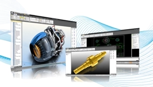
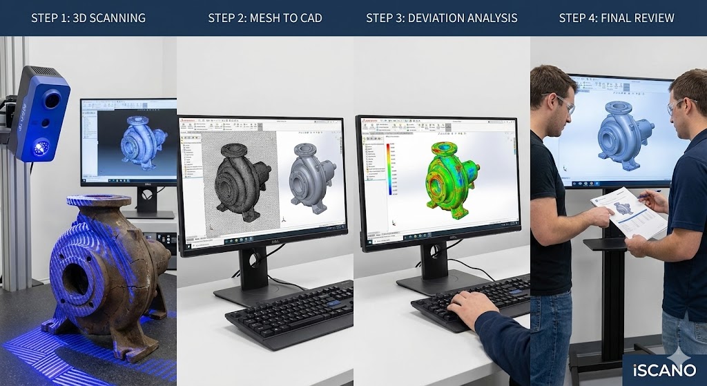
Reverse engineering legacy machine parts by 3D scanning and reconstructing editable parametric CAD models
3D scanning quality control is an inspection methodology that captures the complete geometry of a physical part as a dense point cloud or mesh, then compares that digital model directly against the original CAD design. Unlike traditional inspection—which samples discrete dimensions at selected points—3D scanning captures the entire surface, enabling full-field deviation analysis.
The process works by projecting a laser line, structured light pattern, or other measurement energy onto the part surface while sensors record the deformation of that pattern. Millions of data points are captured in seconds and reconstructed into a high-resolution 3D model. This model is then aligned (or “best-fit”) to the CAD geometry, and software calculates deviations at every point across the entire surface.
The output is typically a color-coded deviation map—green for within tolerance, red for high, blue for low—that gives quality engineers an immediate, comprehensive view of how a part conforms to design intent.
How 3D Scanning Works in Quality Control
A typical metrology-grade 3D scanning quality control workflow follows four steps:
Scan: The operator captures the physical part using a portable metrology scanner. Modern laser and structured-light scanners can capture up to millions of points per second.
Align: Scan data is imported into inspection software and aligned to the native CAD model (such as SolidWorks, CATIA, or NX) using best-fit algorithms.
Analyze: The software generates a full-field deviation color map and dimension tables for every critical feature.
Report: An automated inspection report—often a PDF with pass/fail tables and color maps—is generated for QA sign-off.
What previously required days of CMM programming and measurement can now be completed in hours. For First Article Inspection (FAI) in particular, this compression of the approval cycle means production lines get their green light for mass production significantly faster.
Key Applications in Manufacturing
3D scanning quality control supports several distinct inspection workflows that are central to modern manufacturing quality assurance.
First Article Inspection (FAI)
FAI is the exhaustive verification of the first part off a new or modified production tool. It is often the single largest bottleneck in launching new parts. 3D scanning collapses this cycle by capturing the full part geometry in minutes, automatically comparing it to the CAD model, and generating an instant Go/No-Go verdict with annotated deviation data. Quality teams no longer need to choose which dimensions to check—they get a complete picture on the first article.
Geometric Dimensioning and Tolerancing (GD&T) Inspection
GD&T is the engineering language for specifying and controlling part geometry. Verifying complex callouts—profile of a surface, flatness, true position, concentricity—on curved or organic shapes is impractical with hand tools. 3D scanning makes GD&T inspection visual and comprehensive. An entire airfoil profile or body panel can be verified in one scan, with every callout checked against the full surface rather than a few sample points.
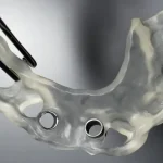
Reverse Engineering for Legacy Parts
Manufacturing plants are full of equipment with missing or corrupted CAD data. When a casting breaks or a mold wears out, there is no digital record to work from. 3D scanning bridges this “data gap” by capturing the physical part as a high-resolution mesh, which skilled engineers then reconstruct into editable parametric CAD models. This enables reproduction of worn or broken components without original drawings.
Tooling and Mold Verification
Injection molds, stamping dies, and forming tools are subject to progressive wear that changes part dimensions over time. By scanning every nth part from production and tracking deviations over time, manufacturers can predict exactly when a tool needs maintenance—before it starts producing scrap. This trend analysis capability turns quality control from reactive to predictive.
Why Manufacturers Are Switching to Non-Contact Scanning
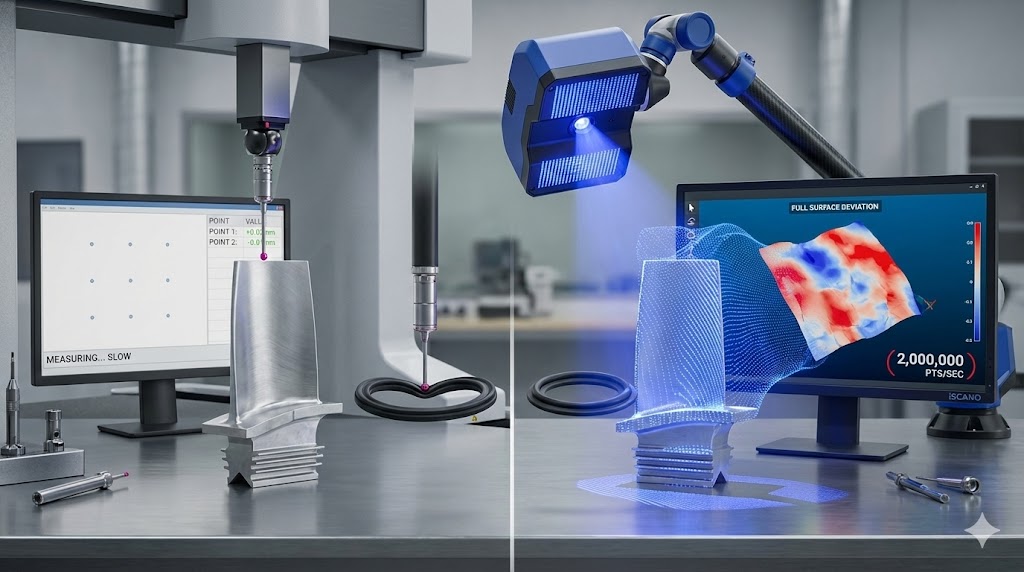
The shift from touch-probe CMMs to non-contact laser scanning is driven by measurable advantages in speed, completeness, and capability.
GD&T inspection of complex geometry with full-surface 3D scanning and color deviation analysis on curved and organic parts
Capability
Traditional CMM
3D Laser Scanning
Data capture rate
1 point per second
Up to 2 million points per second
Inspection coverage
Discrete sample points
Full-surface, every point
Part deformation risk
High for soft/flexible parts
None—non-contact
Complex geometry
Difficult for organic shapes
Handles intricate forms easily
FAI cycle time
Days
Hours
Digital record
Limited measurement logs
Complete point cloud archive
For manufacturers producing parts with complex geometry, soft materials, or stringent surface requirements, non-contact scanning is no longer an upgrade—it is a competitive necessity.
Industries Using 3D Scanning Quality Control
3D scanning quality control is actively deployed across a range of precision manufacturing sectors.
Aerospace
Aerospace manufacturers must verify tight tolerances on components like turbine blades, structural brackets, and nacelle hardware. Full-surface deviation analysis ensures that no hidden deformation—caused by heat stress, material inconsistency, or machining drift—compromises part integrity. 3D scanning also supports digital archiving of as-built geometry for lifecycle compliance documentation.
Automotive
Automotive suppliers face constant pressure to reduce inspection cycle times while maintaining IATF 16949 quality standards. 3D scanning enables rapid FAI for new tooling releases and in-line inspection for powertrain, chassis, and body-in-white components. Virtual assembly—scanning two mating parts and testing fitment digitally before physical tooling—is increasingly used to prevent assembly conflicts.
Industrial Machinery and Tooling
Injection molders and die casters use 3D scanning to monitor tooling wear across production runs. By establishing a tool-wear baseline and scanning production samples at regular intervals, manufacturers can schedule preventive maintenance precisely—eliminating the scrap events that occur when tooling is run past its effective life.
Medical and Precision Engineering
For medical device manufacturers and precision component suppliers, dimensional compliance directly affects patient safety and regulatory standing. Metrology-grade 3D scanning provides the audit-ready digital records required by FDA, CE, and ISO 13485 quality systems, while the micron-level accuracy supports inspection of components with sub-millimeter tolerances.
Frequently Asked Questions
What accuracy can modern 3D scanners achieve in quality control?
Metrology-grade 3D scanners routinely achieve accuracies down to 0.025 mm (25 microns), certified to standards such as VDI/VDE 2634. The actual achievable accuracy depends on the scanner type, part geometry, surface finish, and environmental conditions. For most aerospace and automotive applications, sub-50-micron accuracy is readily achievable with properly calibrated equipment.
Can 3D scanning handle reflective or dark surfaces?
Modern metrology scanners use blue laser or structured light technology that performs well on a wide range of surfaces, including semi-gloss, painted, and dark-finished components. Highly reflective chrome surfaces may require a temporary matte coating, though advanced systems are increasingly able to scan such surfaces without preparation.
What file formats does 3D scanning inspection software use?
Inspection outputs are typically delivered as PDF reports with color deviation maps and dimension tables. For reverse engineering and CAD reconstruction, standard formats include STEP, IGES, and Parasolid (X_T)—all of which are compatible with major CAD platforms including SolidWorks, Inventor, CATIA, and Creo.
Is 3D scanning suitable for shop floor environments?
Portable metrology-grade scanners and articulated measurement arms are designed for shop floor use, with robust environmental compensation and vibration resistance. While lab-grade CT scanners require controlled conditions, portable laser scanning systems can be deployed directly at the production line for real-time in-process inspection.
As manufacturing tolerances tighten and part geometries grow more complex, 3D scanning quality control has moved from a specialist capability to a mainstream production requirement. Manufacturers who adopt full-surface inspection gain earlier defect detection, faster approval cycles, and a complete digital record of every critical dimension. For quality engineers looking to move beyond the limitations of point-by-point measurement, 3D scanning is the practical path forward.
To learn how 3D scanning quality control can be applied to your manufacturing environment, contact the Trinventor technical team at trinventorsolution.com.my.
Thank you for signing up. You will be the first to know the Industry news, upcoming products, latest technology and special promotion.