Quick verdict: 3D printing creates a part that does not exist yet; 3D scanning captures a part that already does. Most businesses start with one, then find they need the other within the first year. If your work involves copying, repairing, measuring or proving an existing component, buy the scanner first. If it involves making something new, buy the printer first.
Additive manufacturing covers a wide spread of machines, materials and ways of working, so the honest answer to “which one do I need?” depends on what you are trying to produce. This guide explains what each technology does, where the two meet, which process suits which job, and how to choose a first machine without buying twice.
It is written for Malaysian engineers, workshop owners and manufacturers who are looking at this equipment seriously for the first time.
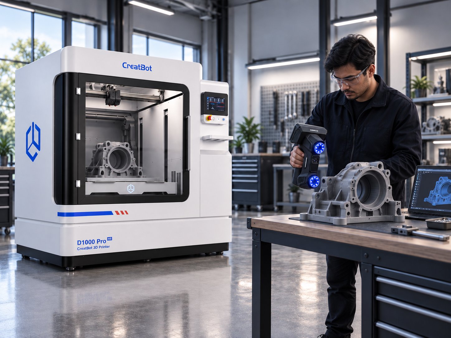
Printing starts with a model that does not exist yet: it is designed, sliced and built up layer by layer
What 3D printing is
A 3D printer builds a part by adding material, one thin layer at a time, until the shape described by a CAD file exists as a solid object. Software slices that file into layers, and the machine follows the resulting path with whatever tool its process uses: a nozzle, a light source or a laser.
Build by layers instead of cutting material away. That one idea is what makes the technology worth owning. Consider a hydraulic manifold with a channel that curves through the body of the part. A milling cutter cannot produce it, because the tool has to reach the surface it cuts. A printer does not care. Consider a jig that needs five different operations on three machines to make conventionally, at a quantity of two per year. Printing it in an afternoon makes more sense than setting up the tooling.
What printing is not is a replacement for machining or moulding in every situation. Layers create direction in the material, so a printed part is rarely equally strong in all directions. Surfaces come off the machine with visible layer lines unless they are finished, and the choice of material is limited to what the process can handle. A printed prototype and a moulded production part are different objects that happen to share a shape.
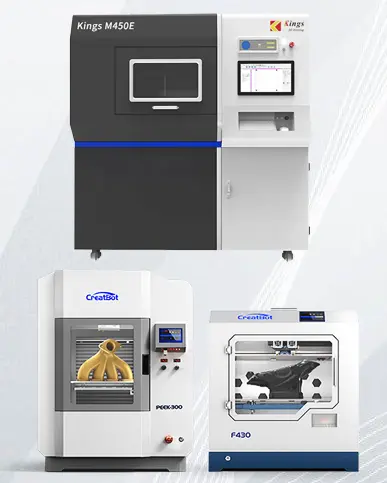
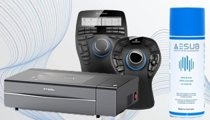
Our 3D printer range runs from compact desktop machines to industrial systems, and the differences matter more than the spec sheets suggest.
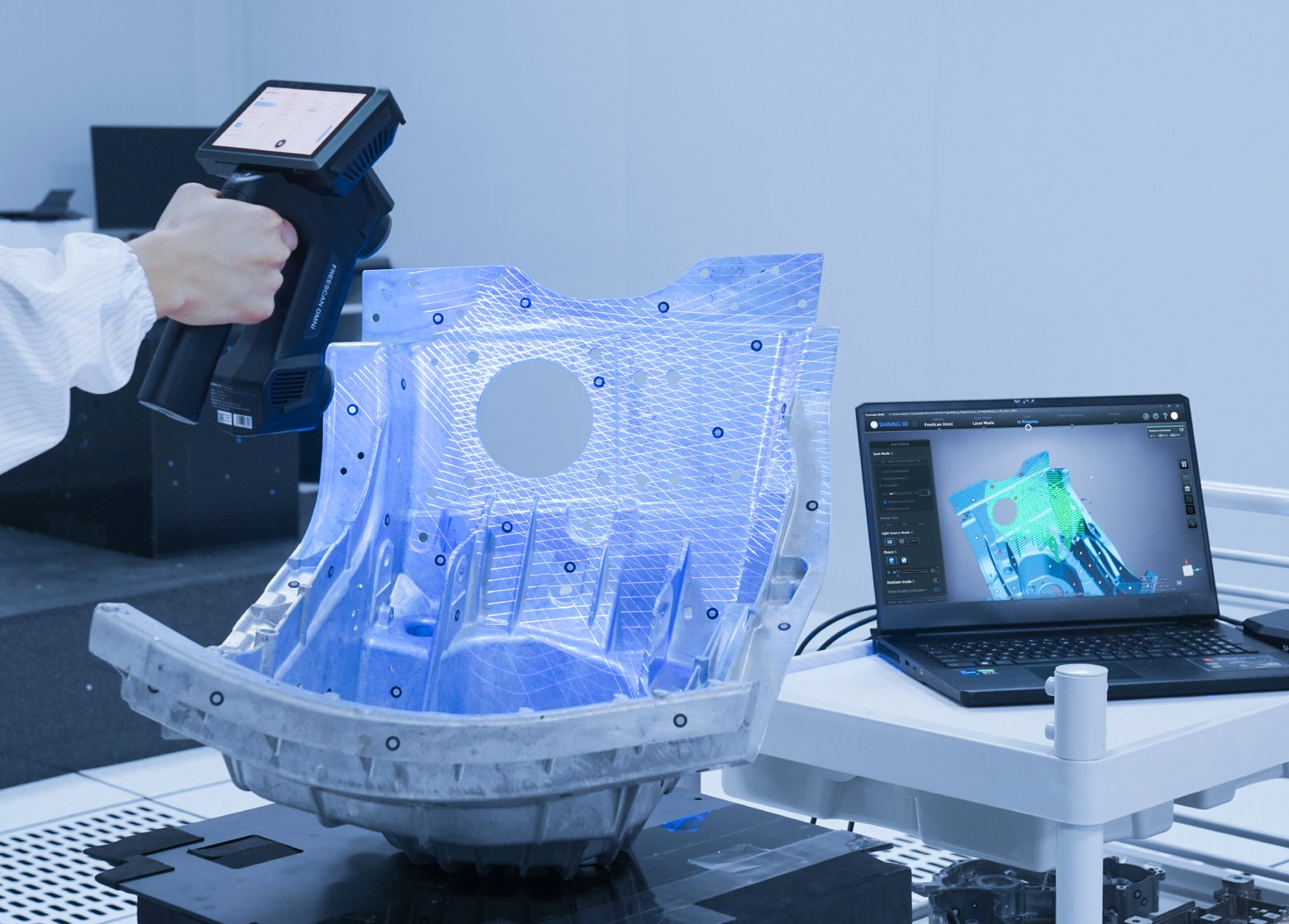
Scanning runs the other way: the geometry already exists, and the scanner measures it point by point into a digital copy
What 3D scanning is
A 3D scanner does the opposite job. It measures the surface of an object that already exists and turns that surface into data: first a point cloud, then a mesh of small triangles describing the shape.
Two things about the output surprise first-time buyers. A scan is geometry, not a model. There are no dimensions, sketches or feature history inside it, so if you want to edit the design rather than copy it, a CAD step is still required. And a scan is dense. A single handheld pass over a medium-sized bracket can carry millions of measurement points, which is a completely different kind of information from five caliper readings at the points someone chose in advance.
A scanner is not a camera in the ordinary sense. Structured-light systems project a pattern onto the object and read how that pattern distorts across the surface. Laser systems sweep a line and read where it lands. Both work out distance by triangulation. Both struggle with the same three surfaces: very dark, very shiny and transparent. That is why a matte spray is normal practice before scanning polished aluminium, chrome or glass.
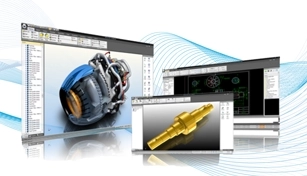
Scanning is not the whole purchase. Capturing the data is one step, and the software that follows does the real work: cleaning the mesh, aligning scans to a common coordinate system, comparing the result to a reference, and converting surfaces into editable geometry. Metrology and CAD platforms such as Geomagic and ZWSoft exist for exactly that, and we supply them alongside the 3D scanners themselves.
Two halves of one workflow
Scan an object, clean up the mesh, modify it, print the result. Each step is unremarkable on its own. Together they solve problems that neither technology solves alone.
Picture a food processing plant with a failed impeller in an old pump. The impeller is discontinued, the drawings were lost years ago, and the pump cannot be replaced without rebuilding the line around it. A scan captures the worn impeller in an afternoon, including the damage. The mesh becomes a CAD model, the eroded surfaces are rebuilt to sensible dimensions, and a plastic version is printed to check the fit and the clearance. Once that test part is right, the final component can be machined or cast from it, or printed directly in metal.
The loop also runs in the other direction. Print a prototype, scan the printed part, compare it against the design file, and you are measuring what the machine actually produced rather than assuming it matched. That habit catches warping, shrinkage and support damage before a batch of parts is finished.
For businesses new to this, the sequence above is the reason both technologies show up in the same quotation.
The main 3D printing technologies, in plain terms
FDM, or material extrusion
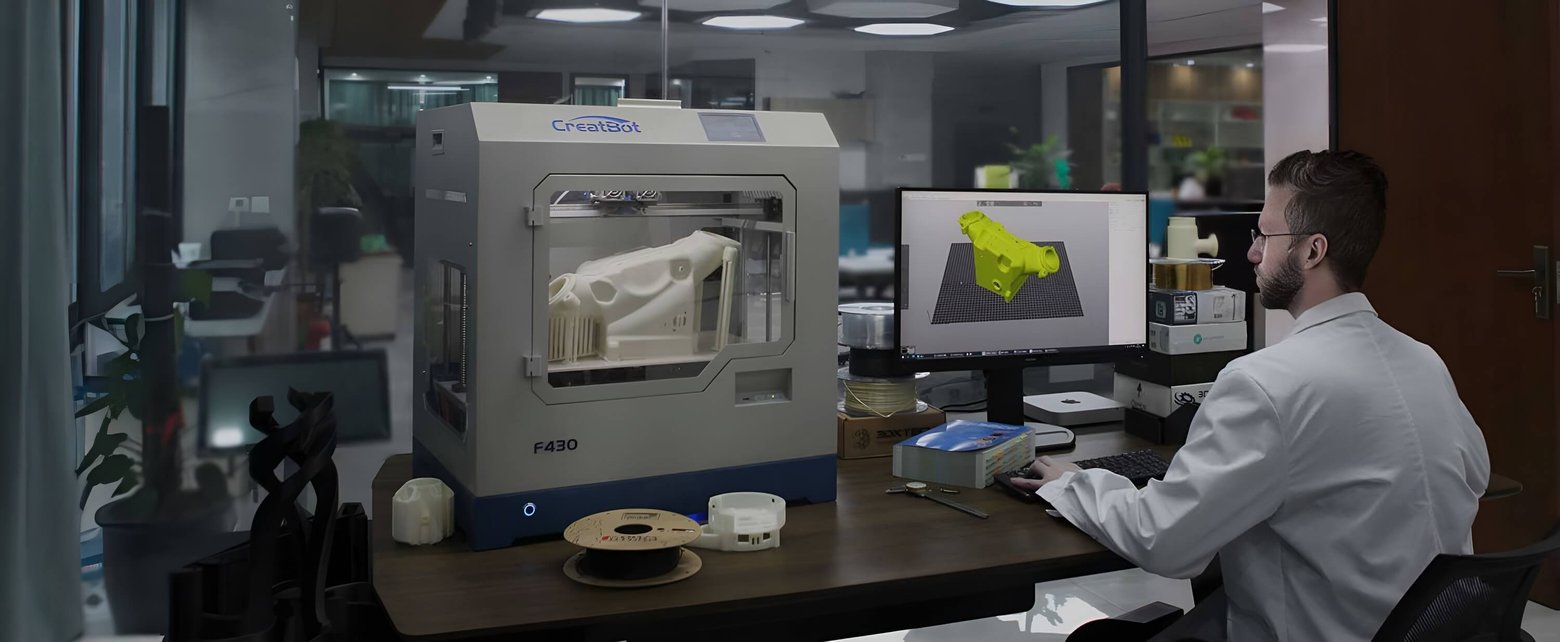
A spool of thermoplastic filament feeds into a heated nozzle, melts, and is laid down along the path the slicing software planned. The nozzle traces one layer, the machine indexes up by a fraction of a millimetre, and the next layer goes on top of the one before. This is the process most people picture when they hear “3D printing”, and it is the one you will find in the widest range of sizes and prices.
FDM suits brackets, jigs, fixtures, enclosures, functional prototypes and larger parts that only need moderate detail. The material list is long: PLA for models and fit checks, PETG for parts that must cope with moisture and slight flexing, ABS and ASA for heat and outdoor exposure, TPU for anything that grips or bends, and nylon, polycarbonate or fibre-filled compounds when stiffness and temperature resistance matter. If your parts need to survive an engine bay or a chemical wash, read our guide to ABS printing and the TPU material guide before you specify anything.
We carry desktop and industrial FDM systems including CreatBot, Bambu Lab, FlashForge and Mingda, with larger and higher-temperature machines for engineering plastics when the part demands it.
Resin, or vat photopolymerisation
Resin printers cure liquid photopolymer with light, layer by layer, either by tracing a laser (SLA) or by flashing a whole layer at once through a screen or projector (DLP and MSLA). The parts come out smoother and finer in detail than anything FDM produces at the same size, which is why dental labs, jewellery workshops and model makers gravitate to them.
The trade-off is size, material cost and handling. Resin is messy before it is cured, so parts need washing and post-curing, and the build volumes are usually smaller than an FDM machine at a comparable price. Choose resin when surface finish, fine features or small precise parts matter more than toughness and build volume.
Powder bed fusion
This is the family that made additive manufacturing a production process rather than a prototyping one. A thin layer of powder is spread across a build bed, then a laser or electron beam fuses a cross-section of the part into it. The bed drops, a fresh layer of powder is spread over the top, and the process repeats until the parts are complete, sitting inside a block of loose powder.
Because the surrounding powder supports the part, supports are not needed in polymer powder bed fusion. Geometries that would collapse on an FDM machine, nested parts, escape channels, living hinges, lattice structures, print without difficulty. The parts are close to isotropic, so strength does not depend on which way the part was placed. Nylon materials such as PA12 are the workhorses, and they are tough enough for end-use components in industrial equipment. Our article on how powder bed fusion works covers the process, material behaviour and applications in more depth.
Metal printing
Metal additive manufacturing takes the same principle to metal powder. Laser powder bed fusion (LPBF) prints stainless steel, aluminium, titanium, maraging steel, inconel and cobalt chrome into fully dense parts with mechanical properties comparable to conventionally made components. EPlus3D covers industrial scale, and FastForm made the technology far more approachable with benchtop LPBF machines; the FastForm shipment milestone is worth reading if you are weighing up metal for the first time.
Metal printing is a different operational commitment from plastic printing. Powder handling, inert atmosphere, safety controls and downstream operations such as support removal, heat treatment and surface finishing all have to be planned for. The parts that justify it are the ones conventional processes cannot make: conformal cooling channels inside a mould, lightweight brackets with organic shapes, or a one-off replacement for an obsolete metal component.
Impossible geometries, conformal cooling, dense metal components
Powder safety, inert gas, post-processing and heat treatment
The main ways to 3D scan
Handheld scanners
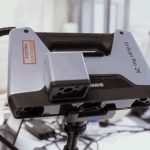
A handheld scanner is the flexible option. You walk around the object, or the object sits on a bench and you move the scanner past it, and the software builds the mesh as you go. Modern units are largely self-positioning, so no arm or tracker is needed, and they handle objects from small machined parts up to a car body.
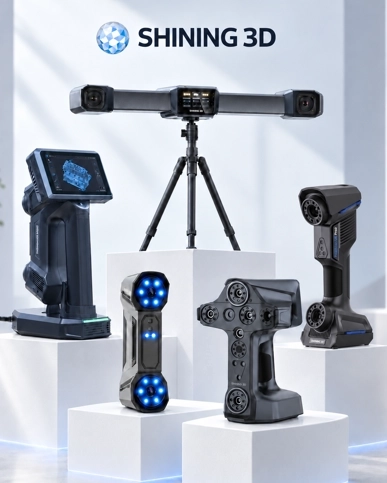
This is the first scanner for most workshops. It is fast, it reaches into most of the part without a fixture, and it is mobile enough to take to a customer site. The trade-off is accuracy, which is good enough for reverse engineering, mould modification, damage assessment and dimensional checks but not the top of the range. Our handheld 3D scanners include Shining 3D and 3DeVOK systems.
Desktop metrology scanners
A desktop metrology scanner trades flexibility for repeatability. The scanner and part are fixed in a known relationship, usually with a turntable or a rotational axis, and the machine is calibrated as an instrument. That setup gives you measurements you can defend in a report and compare between shifts, which is what inspection and first article work requires.
These are the right machines for quality control, incoming inspection, tooling verification and anything where the number has to hold up to scrutiny. They cost more than handheld units and they expect a defined workflow, fixed lighting and controlled conditions. We supply metrology-grade systems such as Shining 3D metrology scanners, and the quality control guide walks through how inspection actually runs.
Photogrammetry
Photogrammetry builds geometry from photographs taken around an object, using the overlap between images to work out where each surface point sits in space. It needs no special hardware beyond a camera and targets, and it scales to things no scanner can treat in one go: a building facade, a boat hull, a sculpture, a large casting.
Accuracy is the limitation. Photogrammetry gives you shape and proportion rather than tolerance, and it struggles with shiny, featureless or flexible surfaces. It earns its place for documentation, archiving, visualisation and rough measurement, and it pairs well with a handheld scanner on large jobs where only a few areas need real precision.
Quality control, first article inspection, tooling verification
Photogrammetry
Large objects and surfaces
Shape and proportion, not tolerance
Camera only
Documentation, archiving, visualisation
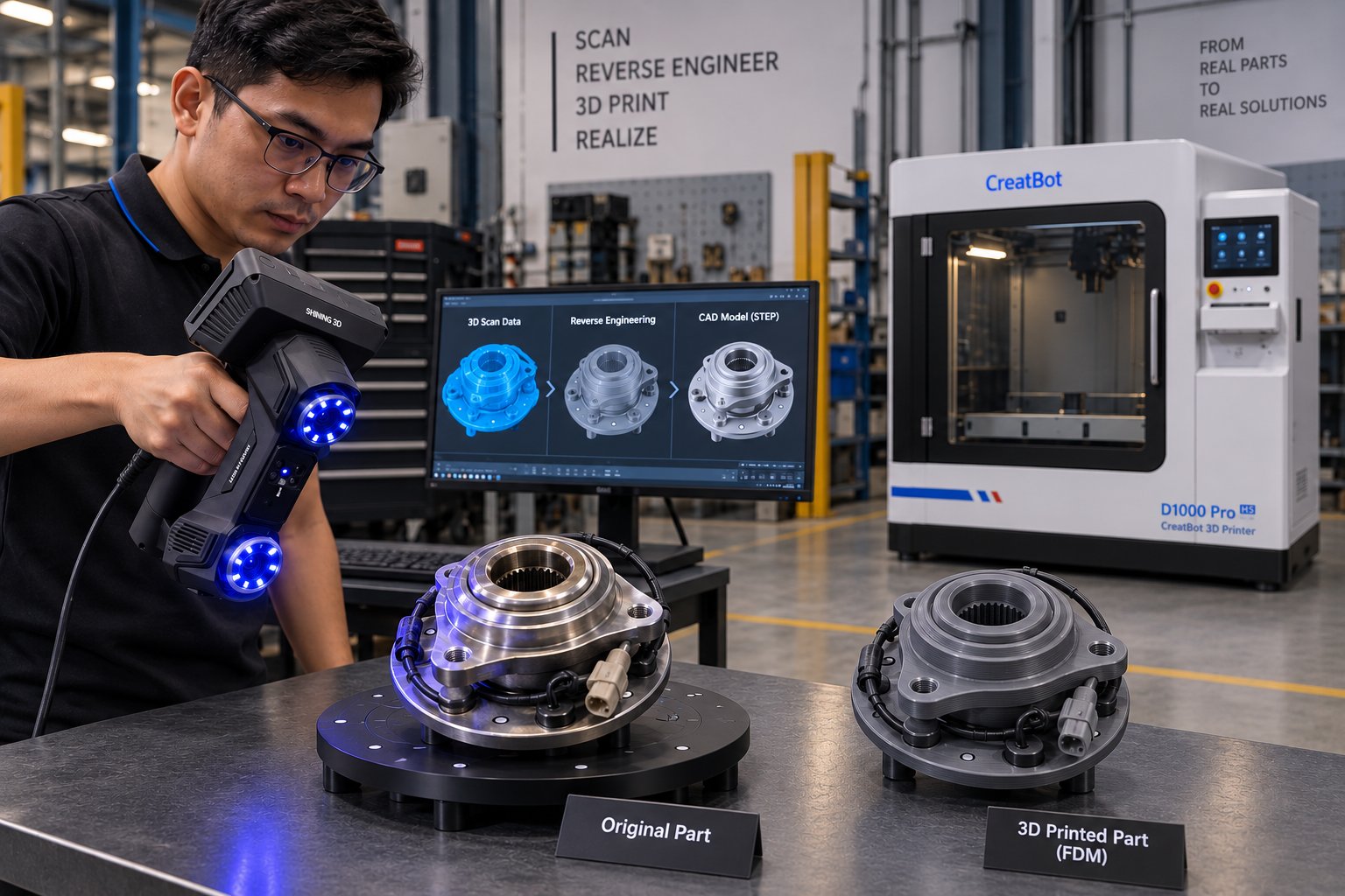
Scan data to reverse engineering to a STEP model to a printed part: one loop, and the reason the two technologies are usually bought together
Reverse engineering: turning a physical part into a usable model
Reverse engineering is the commercial reason most scanners get bought. A part exists, the drawing does not, and it has to be reproduced, improved or replaced.
The work follows a predictable path. Scan the part from enough angles to cover every surface, including the underside and any internal features you can reach. Align the scans, merge them into a single mesh and clean the noise. Then comes the part buyers underestimate: turning that mesh into editable CAD. Some surfaces can be fitted automatically, but flat faces, holes, threads and datum features have to be reconstructed properly if the model is going to be dimensioned, toleranced and manufactured.
From there the model behaves like any other design file. You can thicken a wall that keeps cracking, add a boss for a sensor, change a material, or send it straight to a printer or a machine shop. We cover this workflow under reverse engineering solutions, including the ZWSoft and Geomagic software used at the model-building stage.
Inspection and quality control
Inspection is the fastest-growing use of scanning in Malaysian manufacturing, and for a simple reason. A caliper tells you the size of the features you chose to measure. A scan tells you about the whole surface, including the areas nobody thought to check, and it does so before the part leaves the building.
In practice the scanned mesh is aligned to the nominal CAD model and compared. The software produces a colour map showing where material is missing and where there is too much, with dimensions and deviations listed for the features that carry a tolerance. First article inspection that once took a day of touch probing becomes an hour of scanning and reporting. For a batch, the same measurement plan runs on every part, so the numbers are comparable over time.
Scanning does not make a coordinate measuring machine redundant. Touch probing remains the reference for certain critical features, and the two approaches are usually combined: scanning to see the whole picture and find the anomalies, probing to certify the handful of dimensions that matter most. Our 3D inspection solutions page covers the software side of this.
Where the two technologies meet
Repair and obsolete spares
Machines break in ways that spare parts catalogues do not cover. When a discontinued gear, housing or bracket fails, the options used to be limited to welding it back together or scrapping the machine. Now the damaged part is scanned, the worn areas are rebuilt in CAD, and the replacement is printed or machined from that model. Because the model now exists, the same repair is faster the next time.
Tooling, jigs and fixtures
This is where a printer pays for itself quickly in most workshops. Scan the part or the machine the fixture will mount to, design the fixture to fit that actual geometry rather than a nominal drawing, and print it in a material suited to the loads involved. A soft jaw set or an assembly jig that suits a specific job is a small project, and one that suits the shop floor is usually the result of scanning the thing it has to fit.
Prototyping and custom production
Scan, modify, print, test, repeat. Each cycle is measured rather than estimated, and the physical prototype is available in days. For custom production, the same loop supports one-off parts fitted to an individual customer or machine: a mouthguard or orthotic shaped from a scan of a patient, a sealing jig shaped from a scan of a damaged flange, or a cosmetic cover shaped from a scan of a body panel. Dental and medical production now runs entirely on this pattern, which is why developments such as Amnovis expanding its 3D printed medical device work matter to manufacturers watching the sector mature.
A full ecosystem view
Trinventor Solution covers both sides of the loop: printers, scanners, materials, and the metrology and CAD software that connects them. If you want to see a scan turned into a printed part in one sitting, that is what the Kuala Lumpur showroom is for. See industrial 3D printers and scanners for the equipment combinations used most often.
Which technology do you actually need?
This is the question to answer before anyone quotes you anything. Find your situation in the table below and start there. Most businesses end up needing two rows.
Your situation
Technology that usually fits
Why
Jigs, fixtures, brackets and enclosures in a workshop
FDM
Tough materials, low cost per part, tough geometry, prints in hours
Fine detail, smooth surfaces, small precise parts
Resin
Layer resolution and finish no FDM machine matches at the same size
Complex production parts in nylon, no supports wanted
Powder bed fusion
Powder supports the part, strength is consistent in every direction
Parts that must survive high heat, chemicals or sterilisation
High-temperature FDM
Engineering plastics such as PEEK, PEKK and ULTEM need a heated chamber
Metal components with internal channels or organic shapes
Metal LPBF
Fully dense metal parts no cutting tool can reach
An existing part with no drawing that must be reproduced
Handheld scanner plus CAD
Scanning gives you the geometry; CAD makes it editable again
Proof that a batch matches the design
Metrology scanner plus inspection software
Full-surface comparison against nominal CAD, reported per feature
Inspecting a large weldment or casting on site
Handheld scanner
Portable, self-positioning, covers large objects without a fixture
A digital copy of a building, boat or sculpture
Photogrammetry
Scales to any size with a camera; shape rather than tolerance
A failed or obsolete part to be copied and printed
Handheld scanner plus FDM or metal printing
The scan rebuilds the shape, the print replaces the part
One-off custom parts fitted to an individual
Scanner plus resin or FDM printing
Scan captures the fit, printing produces a single accurate piece
Evaluating additive manufacturing for the first time
Desktop FDM plus a demo of a handheld scanner
Learns the whole loop at the lowest entry point, then scales
How to choose your first machine
Decide whether you are making something or copying something. New parts point to a printer; existing parts with missing drawings point to a scanner. If both, buy in the order that unblocks the next job.
Choose the material before the machine. Temperature, chemical exposure and flexibility requirements eliminate most machines for you. Printing a bracket in the wrong plastic is a wasted project, not a learning experience.
Measure your largest part. Build volume is the specification people most often get wrong. Add margin for the fixture or build plate. If parts are large, look at large-format printers rather than printing in sections.
Set the precision the job actually needs. Reverse engineering and fit checks tolerate a handheld scanner; inspection work needs a metrology system. Buying metrology accuracy for design work spends money on capability nobody uses.
Estimate the volume. A few parts a week suits a desktop machine. Daily production, or several identical parts per build, points to a different class of equipment.
Plan for finishing. Supports must come off, resin must be washed and cured, metal must be stress relieved and finished. Budget the bench space, the tools and the time, because a printer without post-processing capacity becomes a bottleneck. Our post-processing guide lists what each process needs.
Buy locally supported equipment. Service, spares, training and someone to call matter more than a small difference in specification. A machine that stops for a fortnight costs more than it saved.
What it costs to get started
Costs vary too much by specification to quote in a single number, and any article that gives you one is guessing. What can be described honestly is how the categories sit relative to each other.
A desktop FDM printer is the least expensive way into additive manufacturing, and the machine is a modest share of what you will spend in the first year. Filament is the recurring cost, and it changes with material: a quality TPU or a fibre-filled engineering compound costs considerably more per kilogram than everyday PLA.
Resin printing lands in a similar bracket at the small end, but the material costs more per kilogram than filament, and the washing and curing equipment needed to finish parts adds to the initial outlay rather than being optional.
Powder bed fusion sits above both. Polymer PBF machines, powder handling, sieving and surface finishing equipment all scale up together, which is why it usually enters a business when a specific part justifies the investment rather than as a general-purpose addition.
Metal LPBF is the largest commitment in this group, and the machine is only part of it. Metal powder, inert gas supply, extraction, safety controls and heat treatment have to be provided for before the first part is useful. Benchtop metal systems have brought the entry point down considerably, and that is precisely why FastForm shipping a thousand LPBF machines in half a year is worth paying attention to.
On the scanning side, a handheld scanner is the lower entry point, and a desktop metrology scanner costs more because it is built as an instrument. The software is the part buyers forget: inspection and reverse engineering packages are licensed separately from the hardware, and the licence is what turns raw scan data into a report or a CAD model.
There is also a cost that never appears in a quotation: learning time. A printer that nobody trusts produces nothing, and a scanner without a defined measurement routine produces data nobody acts on. Training, a first project chosen deliberately to succeed, and local support are what convert equipment into results.
Frequently asked questions
Can you 3D print a part from a scan?
Yes. A scanned mesh can go straight to a printer for an accurate copy of an existing shape, with no CAD work in between. Where CAD becomes necessary is when you want to change something: add a boss, adjust a wall thickness, correct a worn surface or dimension the model for manufacturing.
Do I need CAD skills to use a 3D printer or scanner?
Not to start. Files can be downloaded or generated from scans, and printing them requires only slicing software. But the value of the equipment rises sharply once someone on the team can edit geometry, which is why CAD software is worth budgeting alongside the hardware.
Is a 3D scanner accurate enough to replace a coordinate measuring machine?
For many checks, yes, and for some, no. A scanner measures the whole surface quickly and finds deviations between the points a probe would have skipped. Touch probing remains the reference method for certain critical features. The practical answer is usually to use both: scan for coverage, probe to certify.
Should I buy a printer or a scanner first?
Buy the one that unblocks the next job. Manufacturing new parts points to a printer. Copying, repairing or verifying existing parts points to a scanner. If you are unsure, a desktop printer plus a demonstration of a handheld scanner on your own part is the cheapest way to find out where the real demand sits.
Can a small workshop print metal parts now?
Yes, and it is no longer an unusual step. Benchtop laser powder bed fusion machines have made metal printing reachable for tool rooms and job shops. It is still a process that demands respect around powder handling, inert atmosphere and post-processing, so plan the safety and finishing workflow before the machine arrives.