3D Scanning for Dental Applications: A Lab and Clinic Workflow Guide
3D Scanning for Dental Applications: A Lab and Clinic Workflow Guide
Quick verdict: A dental lab should begin with a desktop structured-light scanner, because dies, models and impressions are what land on the bench every morning. A clinic that already sends its impressions out gains more from adding a printer than from adding a scanner. Put scanning and printing in the same room and yesterday’s turnaround becomes today’s.
Dental work has always been a measuring job. A crown has to sit on a prepared tooth, a bridge has to meet its neighbours, and a denture has to clear the tissue underneath it. Scanning does not change what needs to be measured. It changes the material you measure, from a plaster model on a bench to a mesh file you can copy, compare, archive and print.
What follows is the chain as a Malaysian lab or clinic would actually run it: what gets scanned, which scanner belongs on which bench, where accuracy earns its keep, how the data travels from scan to CAD to mill or printer, and the faults that waste the most technician time.
What actually gets scanned
The list is longer than most people expect the first time they watch a dental scanner work.
Impressions. Either arch of a conventional impression, scanned directly. This removes the pouring step and takes the expansion of die stone out of the chain. The elastomer surface needs an even matte coating before the sensor can read it.
Models and casts. Working models in plaster or resin, for single units, quadrants or full arches, plus the opposing arch.
Dies. The sectioned individual dies that carry a prepared tooth. This is the classic high-accuracy job in a dental lab, because the margin line lives here.
Full arches and bite records. Upper and lower arches plus the interocclusal record, which together give the design software a relationship to work against.
Wax-ups and trial set-ups. An existing shape can be copied rather than designed again from nothing.
Implant components and milled frameworks. Abutments, bars and machined frameworks are usually scanned to be checked against a design, not to be designed.
Appliance and orthodontic work. Retainers, splints, models for aligner fabrication and the larger shells printed from them.
Where a scanner already sits in the clinic, intraoral scanning replaces the impression itself rather than the model. The arch is captured in the mouth, the file leaves over the internet within minutes, and the lab never handles a tray at all. That split runs through everything below.
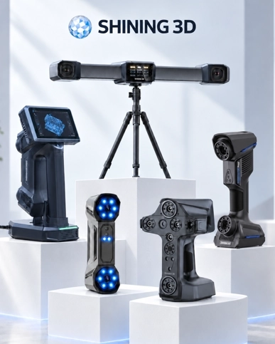
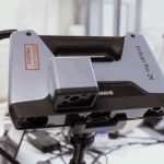
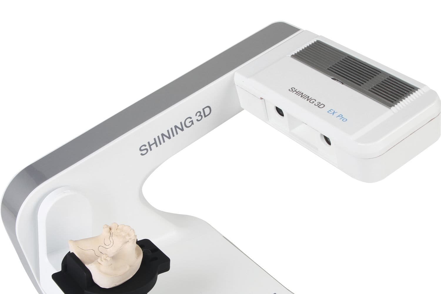
A desktop lab scanner is the workhorse: dies, models and impressions are what arrive at the bench every morning
Scanner types, and which bench each one belongs on
Desktop laboratory scanners
This is the workhorse of a dental lab. A model or a set of dies is loaded onto a rotating platform, a structured light projector patterned in blue sweeps the surface, and twin cameras record how the pattern deforms. Most current units quote accuracy in the single-digit to low-teens micron range, run a full arch in well under a minute, and export open STL, PLY or OBJ files. Check that export list before you buy. A scanner that only writes a proprietary format quietly ties you to one production chain.
Blue light suits dental materials. A narrow blue band sidesteps much of the colour and ambient light that muddies a white light capture, which matters when the subject is chalky white stone, off-white resin or a translucent ceramic. Multi-die mode matters just as much in practice: several dies are scanned in one pass and separated afterwards, and that single feature decides daily throughput on crown and bridge work. The desktop ranges from Shining 3D and EinScan sit in this category.
Intraoral scanners
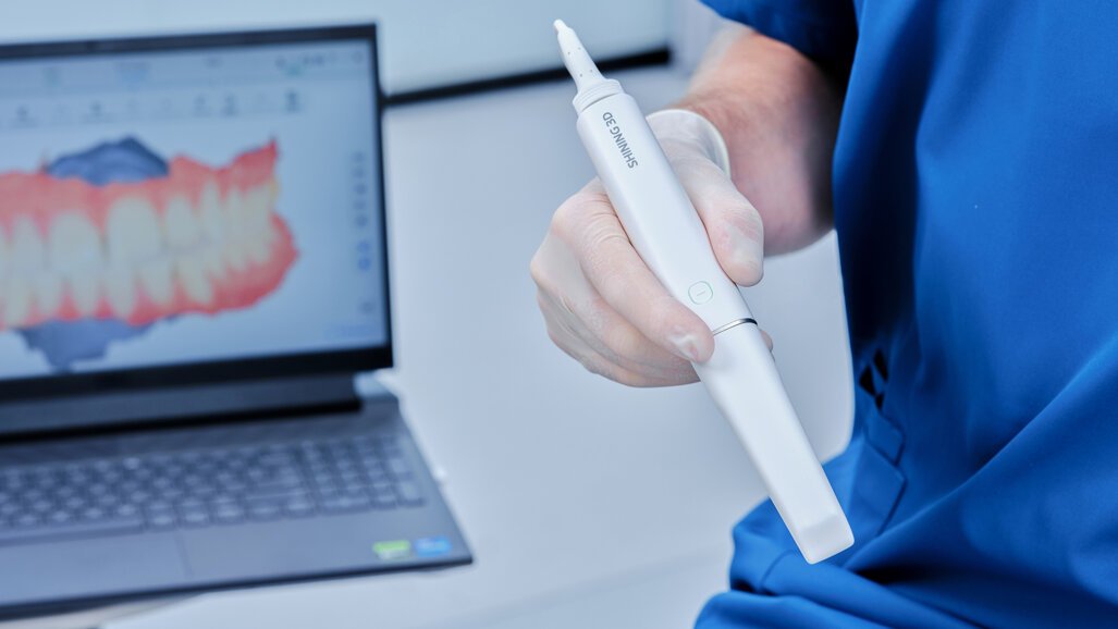
An intraoral scanner is a handheld camera that builds the arch inside the mouth, using one of several optical approaches depending on the wand. The output is the same either way: a mesh of the arch plus a bite record. The real gain is not accuracy for its own sake. It is the removal of the tray, the impression material, the disinfection step, the courier and the plaster, plus the ability to rescan one section while the patient is still sitting in the chair.
Handheld scanners
When the object will not fit a desktop platform, a handheld 3D scanner gives you freedom of movement and a tracking method that does not care how you turn the part. Useful dental jobs include articulated models, larger appliance bodies, full size casts for orthodontic appliances, and the equipment around the lab that occasionally needs a digital copy. A handheld unit also earns its keep outside dentistry, which matters for a lab or workshop that does more than one kind of work.
Metrology scanners
When the question changes from “make me a restoration” to “prove this framework is within tolerance”, you want a measurement device with stated conformity to a testing guideline rather than a design tool. A metrology 3D scanner produces the deviation report, the dimension table and the archived record. Labs building implant bars and machined frameworks, and clinics verifying incoming work, are better served by measurement-grade equipment than by a second design scanner.
Lab scanning versus chairside scanning
Both routes end in an STL file. The differences that decide which one you buy are who does the work, when an error surfaces, and what it costs to correct.
Aspect
Desktop laboratory scanning
Chairside intraoral scanning
Where capture happens
Model, die or impression clamped on a lab bench
Directly in the mouth, in the surgery
Who operates it
Technician, working through a queue of cases
Dentist or chairside assistant, one patient at a time
Physical impression
Still required, and still poured unless you scan the impression itself
Removed from the workflow entirely
Bite record
Scanned separately and matched in software
Captured in the same appointment
Where errors surface
At the model or die stage, usually before the patient has gone home
Immediately, with the patient still in the chair
Rework loop
Requires a new impression and a new cast from the clinic
A section is rescanned in minutes
Accuracy risk sits in
Model preparation, sectioning, coating quality
Saliva and moisture, patient movement, stitching over distance
Best fit
Labs taking work from many clinics, complex prosthetics, appliance fabrication, remakes from existing models
Single units and short spans, orthodontic monitoring, clinics that want same day delivery
Where the outlay goes
A lower capital outlay, with the manual labour of pouring and preparation retained
A larger investment per chair, with labour moved from the lab to the clinic
Data control
The lab holds the file and the archive
The clinic holds the file and decides where it goes
Neither column wins outright. A lab that scans impressions still depends on the clinic’s technique. A clinic that scans intraorally still depends on the lab’s design and production. The reliable pattern in Malaysia at the moment is mixed: intraoral scans arrive for the straightforward cases, and trays still arrive for the awkward ones.
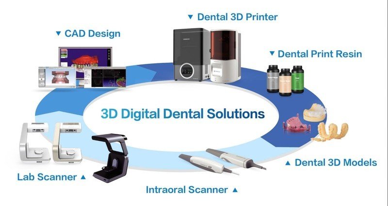
The digital chain runs scan to CAD to print; each stage has its own equipment and the data passes between them unchanged
The workflow from case arrival to delivered work
Eight steps describe almost every digital case, whether it starts with a tray on the doorstep or a file in an inbox.
Step
What goes in
Equipment
What comes out
1. Case arrives
Impression, cast or intraoral scan file
Case log and job card
A case record with a deadline attached
2. Capture
Impression, model, die or full arch
Desktop structured light scanner, or the clinic’s intraoral scanner
A raw mesh
3. Clean up
Raw mesh with noise, spikes and stray islands
Scanner software
A closed watertight model, with dies separated
4. Articulate
Upper arch, lower arch and bite scan
Design software
An aligned virtual model
5. Design
Aligned model, prescription, chosen material
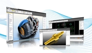
Dental CAD software, or CAD software for laboratory and equipment parts
A design file plus margin line and cement gap settings
6. Prepare for production
Design file, case quantity, blank or resin
CAM module, nesting and slicer software, support and sprue generation
Two things are worth noticing. Step 3 is where most lost time hides, because a badly captured scan cannot be rescued later and the fix is always upstream. Step 8 is the step that most labs skip. Scanning the finished unit back against the design is the cheapest quality check in the building, and it is the same scanner doing the work.
Where accuracy genuinely matters
Accuracy is not one number. It is a set of demands, and they do not sit in the same place in the workflow.
Margins
The margin is the smallest and sharpest feature on the whole model. Everything downstream is built outward from it. If the scan blurs that edge, the design software has to guess where the finish line sits, so the technician draws it by hand, and the variation between one technician and the next becomes the variation in fit. A die scan with a crisp margin is worth more than a scanner spec sheet with a smaller number on it.
Occlusion
Occlusal contacts are judged across the whole arch rather than at one point. An error here rarely shows as an obvious gap. It shows up later as a high spot or a light contact, and it is the reason full arch accuracy deserves separate attention from single unit accuracy. Over a long span the software keeps stitching one view onto the next, and small alignment errors accumulate with distance. A quadrant scan is therefore usually a tighter result than a full arch scan from the same device. Scan in a planned path, complete the arch in one sitting, and keep the wand at a consistent distance from the surface.
Implant interfaces and internal fit
An implant bar or a screw-retained framework has to seat without forcing anything. That is a measurement requirement, not a design preference, and it is the case where a lab benefits from checking a produced part against the design rather than trusting the process. The internal clearance of a restoration, the cement gap set in the design software, is a deliberate and small gap measured in tens of microns. Under-report that clearance in the scan and the unit binds; over-report it and the fit feels loose.
Standards and specifications
A number on a brochure is a claim. A number measured to a published dentistry test method is evidence. ISO 12836 exists precisely for assessing the accuracy of digitising devices used in CAD/CAM for indirect dental restorations, and it works by mounting the object relative to the optical system, which is why it applies to a desktop lab scanner and not to a handheld wand. If a supplier cannot say how an accuracy figure was obtained, treat it as marketing. The general metrology discipline still holds as well: the instrument should be an order of magnitude better than the tolerance you are judging, so the scanner never becomes the dominant source of error.
What the scanner captures is geometry, not a photograph; the colour map on screen is a depth reading rendered for the eye
From scan to CAD to production
The data path is short, but it has three places where cases go wrong.
Format and units. STL remains the common language between scanner, design software, mill and printer, with PLY and OBJ appearing on some systems and 3MF used where colour or texture travel with the geometry. Every format carries an assumption about units, and a millimetre model read as though it were centimetres arrives ten times too large. Check the scale on the first case from any new link in the chain.
Mesh health. A design file needs a closed surface with consistent normals. Holes, flipped faces and self-intersections cause failures that look like a software fault but start as a scan fault. Repair in the scanner software where the original data is still available.
Design intent reaching production. Milling shapes a unit from a solid blank, so the design has to fit the blank. Printing builds a pattern that is either used as it is, invested and burnt out for casting, or pressed. Each route needs its own margin and thickness allowances, and swapping a case from milled to printed without adjusting the design is a common and avoidable mistake.
Where production runs through a casting bench, printed castable patterns have replaced much of the traditional wax work. That method depends on two habits: a resin with predictable burnout behaviour and a printer that produces the same result on a Monday as it does on a Friday. Consistency beats a bolder claim on a data sheet.
Scanning compared with traditional impression taking
Traditional impressions are not obsolete, and no honest supplier will tell you otherwise. An elastomer impression is a well understood, low cost per case method that every clinician has taken thousands of times.
The weaknesses are structural rather than occasional:
Dimensional change. Impression materials and die stone both move as they set, cure and sit in a hot, humid room. A tray poured late is not the same tray poured on time.
Transport and storage. A model is a physical object that can chip, warp, be misplaced or fill a shelf. Scanning turns it into a file you can archive and resend.
Repeatability. A second impression is a second event. A rescan of one section takes minutes and does not restart the case.
Tissue and technique. Some of the harder things to capture, such as a deep margin below the gum line, still favour a well taken impression, and this is where digital workflows remain dependent on the clinician.
What the digital route gives back is a file that does not expire, a design that can be revised without a new impression, and production that starts the moment the design is approved. Most Malaysian labs now run both routes side by side, and a desktop scanner is what lets them accept any case that arrives.
Common scan problems, and how to avoid them
Reflective and glossy surfaces
Impression elastomer, polished metal and glazed ceramic all produce specular reflections that the sensor reads as noise or as nothing at all. An antiglare spray or a light dusting of powder solves it, but it has to be applied in thin, even passes from a distance. Spray too heavily and the coating fills the sulcus and rounds off the margin you are trying to capture. The coating should show the surface texture underneath, not hide it.
Translucent and transparent materials
Light does not stop at the surface of a translucent ceramic or a clear resin. Some of it scatters inside the material and returns to the sensor from somewhere other than the surface, which shows up as a soft, shrunken or noisy edge. A dulling agent is the usual answer. Without it, margin accuracy on these materials simply cannot be trusted.
Undercuts, deep pockets and shadowed geometry
Structured light needs line of sight. No software recovers a surface that was never captured. Tilt the model and rescan from additional angles, split a section, or block out an undercut before you start. Handheld scanners help here because you can move around the object rather than moving it around a fixed sensor.
Moving patients
Chairside, the scanner is stitching views onto a reference that has no fixed relationship to the object. Chair movement, a restless tongue, an assistant’s suction tip crossing the field mid-scan, all of it adds error. Dry the field, ask the patient to keep still and pause the scan while anything crosses it. If a scan starts drifting, stop and restart the section rather than fighting the software.
Moisture, saliva and blood
The single largest chairside accuracy fix is a dry field. Fluid film scatters light, and an otherwise excellent intraoral scanner cannot read through it. On the lab side, a wet impression should be dried before coating.
Ambient light
A window or an operatory light aimed at the subject washes out the projector pattern, and a bright room with the light angled at the bench does the same to a desktop unit. Move the light away from the field rather than simply dimming the room.
Optics and calibration
Trim gypsum, resin dust and fingerprints all settle on a scanner lens, and a dental lab produces all three in quantity. Clean the optics the way the manual specifies, cover the machine when it is not in use, and calibrate on the schedule the manufacturer gives you. A scanner that has drifted out of calibration fails quietly: files still look right on the screen.
Environment and storage
Heat and humidity are hard on resin models, wax-ups and printed patterns. A pattern that sat in a parked car before the afternoon investment stage is not the same object that was printed that morning, and no scan made before the drive can fix it after.
Where 3D printing fits downstream
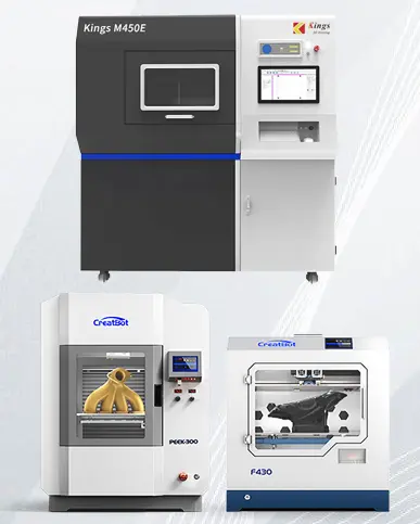
Scanning produces a file. Something still has to turn it into an object, and this is where a lab’s own DLP or MSLA resin printer or an SLA printer earns its place beside the scanner.
Working models. Arches are printed hollow to save resin, with removable dies printed separately and seated into the base. Layer heights in the dental range run from the fine end, around twenty five microns, up to a hundred microns. Margin critical work belongs at the fine end.
Casting patterns. Castable resin is printed, invested and burnt out in place of hand waxed patterns.
Guides, splints and temporaries. Anything that spends time in the mouth raises questions about the material and the process behind it, so the resin and the validated workflow matter more than the printer’s speed.
Try-ins and provisionals. Printed shapes let a case be checked before an expensive blank is milled.
Orthodontic and appliance work. Models for thermoformed appliances and the shells themselves are a natural fit for resin printing.
Printing also removes the plaster room from the workflow. No die stone, no vacuum mixer, no trimming dust. For a lab in a commercial unit where space and airborne dust are both constrained, that is a practical gain on its own.
Planning this for a Malaysian lab
A few local realities decide whether the equipment settles in or becomes a shelf ornament.
Dust and humidity. Gypsum dust and a humid climate are the two conditions scanner optics dislike most. Invest in covers, a closed storage cabinet and a dehumidifier for the materials cabinet.
Power and layout. Many labs operate in shoplots and upper floor commercial units on a single phase supply. Add up the printer, the curing unit, the mill, the vacuum and the scanner before you install, and leave the printer somewhere that ventilation and resin handling are sensible.
Support and spares. A scanner that is down for a month costs more than a slower machine that never stops. Buy from a supplier who stocks consumables locally, services calibration and trains the technicians who will actually run it. We keep a showroom in Kuala Lumpur for exactly that reason, so a case can be scanned on real material before a decision is made.
People. A scanner shifts work rather than deleting it. Somebody has to learn margin marking, mesh repair and nesting, and that person is usually the technician who already understands the models.
Regulatory paperwork. Items made to sit in a patient’s mouth fall inside Malaysia’s medical device framework, and the Medical Device Act 2012 (Act 737) is where that framework starts. Confirm with the Medical Device Authority, or a regulatory advisor, how your own products are classified and what records your customers will expect to see. Keep a digital archive either way: design file, scan of the finished unit and the batch record are cheap to keep and hard to reconstruct.
Which order to buy in
A lab with no digital equipment should buy the scanner first. It digitises work you are already being paid to do, it needs no new materials and no new skill set on day one, and it makes every case you already accept faster to produce. The printer follows, because it turns those files into models and patterns without a plaster room.
A clinic should reverse the order unless it is already handling its own design work. A printer lets a clinic make models, try-ins and guides from scans taken anywhere. An intraoral scanner only pays off once the clinic’s lab partners are set up to receive files, and until then it adds a capital cost without removing the tray.
Frequently asked questions
Can a desktop scanner scan an impression, or only a cast?
Both, on most current units. Scanning the impression removes the pouring step and takes die stone expansion out of the chain, but the elastomer needs an even matte coating first and the impression has to be dimensionally stable at the moment it goes on the platform. Many labs scan impressions for accuracy critical work and scan casts for everything else.
How accurate does a dental scanner need to be?
Finer than the feature you are judging. Lab scanners are commonly specified in the single-digit to low-teens micron range, and intraoral scanners produce results in the tens of microns over a quadrant, with more deviation accumulating across a full arch. The honest answer is to ask how the figure was tested and to trial the scanner on your own dies and margins.
Do I need powder or spray on every model?
No. Most modern dental scanners read matte gypsum and matte resin models without preparation. Coating is needed where the surface is glossy, translucent or metallic, which covers impressions, glazed ceramics, some high-translucency materials and machined metal parts.
Can an intraoral scanner handle a full arch accurately enough for a denture?
It can for many cases, and it is common practice now. Be aware that full arch accuracy is where stitching error accumulates most, so the technique matters: a planned scanning path, a dry field and one uninterrupted session. Where a case is more demanding, a scanned impression or a scanned cast on a desktop unit remains a sound route.
What format does the lab send the clinic?
STL, as a rule, because every design platform, mill and printer accepts it. PLY, OBJ and 3MF also appear where colour, texture or extra metadata need to travel. Agree the format and the units at the start of the relationship, and check the first case’s scale before it reaches a machine.