High Temperature 3D Printing Material: PEEK vs PEKK vs ULTEM Guide
Quick verdict: PEEK holds the highest service temperature and the broadest chemical resistance of the three, but it needs a chamber close to 250 °C, which rules out most printers. PEKK delivers PEEK-class mechanical performance with a far easier process. PEI prints more predictably than either and carries the aerospace flammability approvals that cabin and interior work demands.
Picking a high temperature 3D printing material settles several questions at once: which printer you have to buy, how long the part survives in service, and whether a quality or certification team will sign it off. This guide compares PEEK, PEKK and PEI on thermal limits, strength, chemical resistance and processing requirements, then maps each material to the aerospace, automotive, medical, oil and gas and electronics work where it earns its place.
All three sit in the same broad family of high-performance polymers, yet on the shop floor their behaviour diverges sharply. One asks for a chamber close to 250 °C and will not bend on it. Another prints reliably at 140 °C. One leads on fatigue life, another on ease of printing and layer adhesion.
What makes a polymer high temperature?
Engineering thermoplastics earn that label when they keep working where ordinary materials give up. ABS, nylon and polycarbonate soften, creep or warp well before those extremes, and they suffer under repeated thermal cycling or in contact with aggressive chemistry.
Judgement comes down to three questions. How much mechanical function does the material retain at sustained temperatures above 200 °C? How does it cope with thermal cycling? And how stable is it in chemically hostile surroundings? In additive manufacturing, those properties open the door to replacing machined metal, which trims part weight, takes corrosion out of the equation and allows internal geometries a milling cutter cannot reach.
The three materials engineers ask about most are:
- PEEK (polyether ether ketone): the reference point for extreme heat and chemical exposure, and the yardstick every other engineering thermoplastic gets judged by.
- PEKK (polyether ketone ketone): a PAEK with a different ketone-to-ether ratio, usually printed in its AM-grade PEKK-A form, which trades a little thermal ceiling for much easier processing.
- PEI (polyetherimide), the polymer sold under the trade name ULTEM: an amorphous material with decades of certified aerospace use and the widest processing window of the three.
PEEK and PEKK are semi-crystalline, so their final properties depend on how well the part crystallises during the build. PEI is amorphous, which is why it tolerates a broader range of settings and keeps results even across large build volumes.
PEEK: the benchmark for extreme environments
The mix of tensile strength, chemical stability and heat resistance in PEEK puts it at the head of the PAEK family. When nothing else survives the duty cycle, this is the material engineers reach for.
The numbers tell the story. Continuous service temperature runs to roughly 240 °C, the melting point is close to 343 °C, and the glass transition temperature lands around 143 °C. In practice the material only begins to soften meaningfully at temperatures that would already have ruined most thermoplastics, which leaves designers a wide margin to work with.
Chemical resistance is just as broad. Fuels, hydraulic fluids, lubricants, seawater, most acids and alkalis, plus steam, all leave PEEK largely untouched. Repeated sterilisation cycles leave those properties intact as well, which is how the material became common in medical device production and in food plants, where hygiene and service life both have to be guaranteed.
In aerospace you find PEEK in structural brackets, air ducting and parts that have to ride out years of vibration and thermal cycling. Oil and gas uses it for downhole tooling, where pressure resistance and chemical stability narrow the field to very few polymers. Electrical work leans on a different side of the material: dielectric strength, arc resistance and a UL94 V-0 flame rating, which suit high-voltage connectors and insulating components.
The catch sits on the equipment side, and it is a real one. PEEK is the hardest of the three to print, and it will not forgive a machine that cannot hold chamber temperature.
PEKK: PEEK-class performance, easier processing
PEKK occupies the middle ground between PEEK and PEI. Its ketone-to-ether ratio differs from PEEK’s, which changes how it crystallises and lowers the temperature you need to process it. The result is a material that gives you most of PEEK’s mechanical and thermal behaviour with far less trouble at the printer.
The AM-grade formulation, PEKK-A, prints with a nozzle around 340 to 360 °C and a chamber temperature of approximately 140 °C. Compare that with PEEK and its demand for a chamber approaching 250 °C. The lower thermal requirement widens the list of industrial machines that can handle the material, since ultra-high-temperature chambers stop being mandatory.
Slow crystallisation is the second advantage. It produces better bonding between layers and lowers the risk of warping and cracking as the part cools. Where PEEK’s faster crystallisation can cause delamination in large, complex geometry, PEKK tends to produce more predictable results.
Mechanically, PEKK matches PEEK closely: tensile strength for filament typically falls in the 90 to 100 MPa band, chemical resistance is broadly similar, and heat deflection temperature sits above 200 °C depending on grade and print orientation. One characteristic is worth flagging before you commit. Because PEKK is a PAEK, its mechanical properties are orientation-sensitive in print, so raster orientation matters more than it does with PEEK. In static load applications that is rarely a problem, and PEKK suits functional prototypes and end-use parts in oil and gas, aerospace and industrial equipment. Aerospace qualification programmes are maturing, which is steadily making PEKK a viable alternative to established PEI grades.
PEI: aerospace-grade stability and the easiest process
PEI (polyetherimide) is amorphous rather than semi-crystalline, and that single structural difference explains most of its behaviour. The broader, more forgiving processing window makes consistent results over large build volumes much easier to achieve than with either PAEK material.
Two grades dominate additive manufacturing. They are far enough apart that they should be treated as separate options rather than one material with a setting tweak.
PEI 9085: the workhorse
With a glass transition temperature near 186 °C and a continuous service temperature around 160 °C, PEI 9085 covers demanding thermal environments while staying much easier to print than PEEK. Its flame, smoke and toxicity performance, compliant with FAR 25.853, plus low smoke toxicity, made it the preferred material for aircraft interior parts. Printing runs at a nozzle temperature around 330 °C with a chamber at approximately 170 °C, well inside the capability of many industrial FDM systems.
PEI 1010: more heat, more machine
PEI 1010 goes further, with a continuous service temperature that reaches approximately 200 °C, better chemical resistance and approval for food-contact applications where the resin carries the appropriate manufacturer certification. The trade-off is thermal. Nozzle temperature climbs to around 450 °C and chamber temperature to roughly 210 °C, which puts the material in the same equipment class as PEEK, though with the processing behaviour of the PEI family.
Where PEI beats both PAEK materials is certification pedigree. PEI 9085 has been qualified on a long list of commercial and military aircraft programmes, which gives procurement and quality teams a documented regulatory path. In many aerospace contexts that path simply does not exist yet for PEEK, however good its mechanical data looks.
Thermal performance in detail
Heat is usually the reason an engineer starts looking at these materials in the first place, so it deserves a closer look than a single headline number.
| Material |
Structure |
Continuous service temperature |
Heat deflection temperature |
Notes |
| PEEK |
Semi-crystalline PAEK |
Approximately 240 °C |
Above 250 °C |
Glass transition around 143 °C, melting point near 343 °C; the highest ceiling of the three |
| PEKK |
Semi-crystalline PAEK |
Around 200 °C |
Above 200 °C, grade and orientation dependent |
Sits between PEEK and PEI in sustained load at temperature |
| PEI 9085 |
Amorphous PEI |
Approximately 160 °C |
Approximately 186 °C |
For an amorphous polymer the glass transition is the practical ceiling |
| PEI 1010 |
Amorphous PEI |
Approximately 200 °C |
Approximately 200 °C |
Narrows the gap to PEKK while keeping the easier PEI process |
Short-term resistance runs well beyond the continuous figures for all three materials, which matters for parts that see occasional excursions rather than a constant soak.
Reading the table against a real application is what counts. Where a part carries hot fluid, sits beside an engine or forms part of a heated air path, PEEK’s headroom pays for itself in service life. PEKK handles the same kinds of duty one step lower on the temperature scale. Where a part stays inside a normal thermal envelope, such as an interior panel, an air management duct or a bracket, the certification record behind PEI 9085 usually settles the choice before temperature even enters the discussion.
Mechanical properties: how the three compare under load
All three materials leave commodity engineering plastics far behind. The differences among them are what matter for load-bearing work.
| Property |
PEEK |
PEKK |
PEI 9085 |
PEI 1010 |
| Tensile strength |
90 to 100 MPa |
90 to 100 MPa |
Approximately 90 MPa |
Approaching 100 MPa |
| Tensile modulus |
Approaching 3.6 GPa |
PEEK-class, grade dependent |
Approximately 2.2 GPa |
Above PEI 9085 |
| Flexural strength |
Above 140 MPa |
PEEK-class |
Approximately 130 MPa |
Above PEI 9085 |
| Elongation at break |
Low |
Low to moderate |
Around 11 percent |
Above PEI 9085 |
| Fatigue behaviour |
Among the best of any thermoplastic |
Good, orientation-sensitive |
Adequate for the duties it is approved for |
Improved over PEI 9085 |
PEEK’s fatigue resistance under cyclic loading is the standout, and it explains why the material still leads in structural brackets, pump housings and anything else that has to take years of dynamic load in a punishing environment.
PEKK runs close to PEEK on tensile strength, with the orientation caveat noted earlier. Plan the build orientation around the load path rather than accepting the default, and it performs very well in static loading.
PEI is the softer of the two families: lower modulus and lower flexural strength than PEEK or PEKK. It answers with toughness. Elongation at break of around 11 percent on PEI 9085 gives it better behaviour in impact scenarios, and PEI 1010 improves on the mechanical figures while adding thermal capability.
For anything fatigue-critical, which means cyclic pressure, vibration and thermal cycling combined, PEEK keeps the advantage over the long term. That is much of the reason it still dominates in aerospace secondary structure work and in downhole oil and gas tools.
Chemical resistance
All three materials resist a broad range of industrial chemistry, but the differences are worth understanding before you specify one for a chemical environment.
| Material |
Resists well |
Where it is weaker |
| PEEK |
Seawater, fuels, hydraulic fluids, lubricants, most acids and alkalis, steam sterilisation, cleaning chemicals |
Very little in normal industrial service |
| PEKK |
Broadly the same list as PEEK |
Lower crystallinity means some solvents can work their way in over very long exposure times |
| PEI 9085 and 1010 |
Hydrocarbons, alcohols and aqueous solutions |
Ketones, esters and chlorinated solvents, particularly when the part runs hot |
PEEK is close to inert across the widest chemical range of the three, and repeated contact with steam or cleaning chemicals leaves its properties essentially unchanged. That is why it became the standard choice for chemical processing equipment, downhole oil and gas hardware and food plants, where an incompatible material is a failure risk rather than an annoyance.
PEKK performs adequately in most industrial chemical environments, with the permeability caveat above reserved for very long exposure to particular solvents.
For PEI, the picture depends entirely on the process. Aerospace and automotive interiors rarely bring a part into contact with the solvents that trouble the material, so the limitation never comes up. In chemical processing, the same limitation can disqualify it outright. Check the specific medium and the service temperature together, not one without the other.
Industrial applications by material
Theoretical differences only matter once they translate into application fit, so here is where each one is most often used.
Aerospace
PEI 9085 remains the reference material for cabin interiors: overhead stowage bins, interior panels, air ducting and other non-structural components. FAR 25.853 flame, smoke and toxicity compliance drives that, and the certification record makes the choice straightforward for procurement. PEEK appears in higher-temperature zones and in structural brackets where strength for weight and fatigue life edge out PEI. PEKK is emerging as an option for ducting and non-structural cabin air parts, where a friendlier process window means fewer scrapped builds.
Automotive
PEEK owns most under-bonnet work, in sensor housings, connector bodies and fluid fittings, where heat and chemical resistance decide the material. PEKK has taken ground where processing ease counts for more than the final few degrees of heat tolerance, such as structural brackets and fuel system parts. PEI 9085 covers interior trim and thermal management components, where flame retardancy is the deciding property.
Medical and surgical
PEEK has a long history in medical device manufacturing, from surgical instrument handles to sterilisation tray components and non-implantable device housings. Standing up to repeated autoclave cycles without degrading is a practical advantage no other option in this group matches as cleanly. PEKK is used in some medical tooling applications. PEI 1010 brings food-contact approvals, depending on formulation, which makes it useful for medical production equipment and tooling in food plants.
Oil and gas
Downhole conditions bring high pressure, corrosive fluids and constant heat together, which makes them among the hardest places to specify a part for. PEEK owns this sector, appearing in seal housings, sensor protectors and completion tools, where pressure, chemistry and heat all have to be handled at once. PEKK serves similar duties at lower severity, where easier processing shortens lead times.
Electrical and electronics
PEEK and PEI dominate electrical work. Insulation and high-voltage connector designs lean on PEEK’s dielectric strength, arc resistance and UL94 V-0 rating. Radio-frequency transparency gives PEI a niche in radomes and antenna hardware. PEKK covers busbar supports and medium-voltage insulators where its property set is sufficient.
What your printer must deliver
This is where the gap between “can print” and “prints reliably” decides the project. Nozzle temperature is only half of the requirement, and often the smaller half. Chamber temperature is the real differentiator.
Industry analysis of machines marketed for high-performance polymers found that roughly 85 percent of them cannot print PEEK reliably, 77 percent fall short on PEI 1010, and nearly half never reach the chamber temperature that PEI 9085 needs for consistent results. Those figures are worth remembering when a machine’s headline nozzle temperature is quoted in isolation.
| Material |
Minimum chamber temperature |
Minimum nozzle temperature |
Minimum bed temperature |
Print difficulty |
| PEKK |
140 °C |
350 °C |
150 °C |
Moderate |
| PEI 9085 |
170 °C |
330 °C |
180 °C |
Moderate |
| PEI 1010 |
210 °C |
450 °C |
220 °C |
High |
| PEEK |
250 °C |
450 °C |
250 °C |
Very high |
Of the three, PEKK gives you the most room for error. A chamber at approximately 140 °C puts it within reach of a much broader range of industrial systems, and its slower crystallisation reduces internal stress during cooling, which shrinks the chance of warping or delamination on large builds.
PEI 9085 sits in the middle, needing roughly 170 °C of chamber temperature, which many industrial FDM systems with heated enclosed chambers can hold. PEI 1010 raises the bar to about 210 °C and lands in the same equipment class as PEEK.
PEEK asks the most of the machine. To keep parts from warping and to develop full mechanical properties, the chamber has to reach roughly 250 °C, close to where the material itself melts. Let the chamber run cool and you get warped, delaminated parts that never crystallised properly, with strength well below what the data sheet promises.
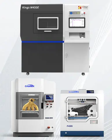
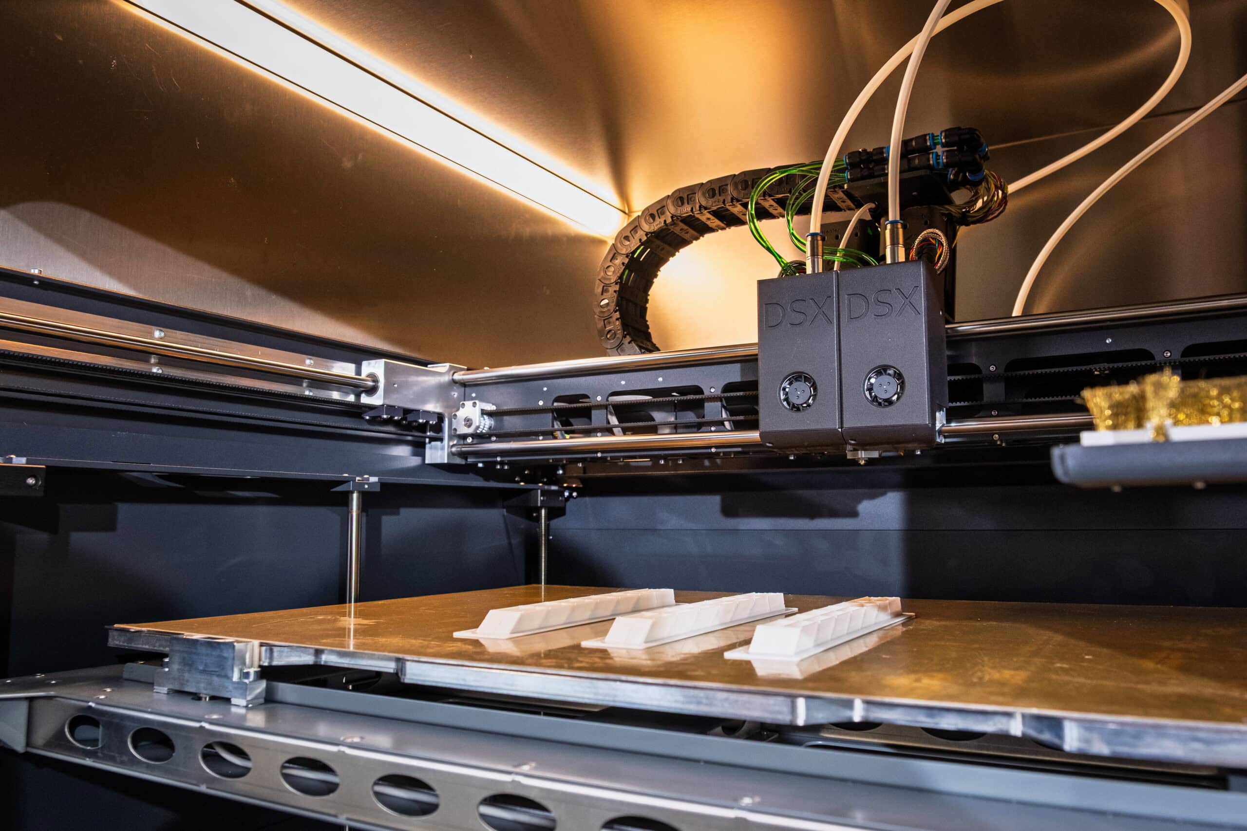
When you compare machines for this class of material, weight the chamber specification above everything else: chamber size and maximum temperature, hot end rating, bed temperature, and whether the chamber is actively heated rather than merely enclosed. Industrial FDM platforms such as those from CreatBot and Intamsys are built around these requirements, with heated chambers and high-temperature hot ends intended for PAEK and PEI materials.
Decision guide: choosing the right material
Match the requirement to the material that meets it with the least processing complexity. Work through these four cases.
- Choose PEEK if your application needs the highest continuous service temperature above 200 °C, the strongest chemical resistance available in a thermoplastic, or the longest fatigue life under repeated load. It is the right answer for downhole oil and gas hardware, hot-zone aerospace brackets and chemical plant components where nothing about heat or chemistry can be compromised. Plan for the most demanding printer specification of the group: a chamber close to 250 °C.
- Choose PEKK if you need PEEK-class performance with easier processing and wider machine compatibility. It suits large industrial parts where PEEK’s fast crystallisation creates warping risk, companies moving from PEI to PAEK materials, and applications whose thermal requirement sits below the PEEK threshold. Expect roughly 90 percent of what PEEK delivers, with a much easier process to manage.
- Choose PEI 9085 if the part must satisfy FAR 25.853 flammability requirements, your supply chain already carries aerospace material qualifications, or your duty cycle stays inside roughly 160 °C continuous. It runs on more machines than the other three options and has the shortest route to aerospace sign-off.
- Choose PEI 1010 if you want PEI’s certification profile but need more thermal resistance than PEI 9085 provides. Accept the trade-off: nozzle temperatures around 450 °C and a 210 °C chamber, which puts it in the same printer class as PEEK.
Material comparison at a glance
| Property |
PEEK |
PEKK |
PEI 9085 |
PEI 1010 |
| Material class |
Semi-crystalline PAEK |
Semi-crystalline PAEK |
Amorphous PEI |
Amorphous PEI |
| Maximum continuous service temperature |
Approximately 240 °C |
Around 200 °C |
Approximately 160 °C |
Approximately 200 °C |
| Tensile strength |
90 to 100 MPa |
90 to 100 MPa |
Approximately 90 MPa |
Approaching 100 MPa |
| Chemical resistance |
Outstanding |
Very good |
Good |
Good |
| Flammability |
UL94 V-0 |
UL94 V-0 |
FAR 25.853 |
FAR 25.853 |
| Chamber temperature required |
Approximately 250 °C |
Approximately 140 °C |
Approximately 170 °C |
Approximately 210 °C |
| Print difficulty |
Very high |
Moderate |
Moderate |
High |
| Typical application |
Downhole tools, high-temperature brackets, chemical processing |
Large industrial parts, ducting, air management |
Aircraft interiors, structural brackets, connectors |
Higher-temperature certification work, food-contact tooling |
Frequently asked questions
Can PEEK parts be sterilised repeatedly?
Yes. PEEK tolerates steam sterilisation and repeated contact with cleaning chemicals without meaningful degradation, which is why it is common in surgical instrument handles, sterilisation tray components and non-implantable device housings. Keep the cycle inside the material’s continuous service temperature and the properties hold up.
Is PEKK as strong as PEEK?
Tensile strength is comparable, typically 90 to 100 MPa for filament. The differences appear elsewhere: PEEK keeps the advantage in long-term fatigue, while PEKK is more sensitive to print orientation and depends on well-planned raster paths to reach its potential. For static loading, PEKK performs very well.
Why do these materials need a heated chamber at all?
Cooling rate decides how the part crystallises and how much internal stress builds up between layers. A heated chamber slows cooling, improves layer bonding and reduces warping. Without one, semi-crystalline materials such as PEEK and PEKK may never reach full crystallinity, and even amorphous PEI will crack or lift from the bed on large parts.
Do I need a dedicated machine for high-temperature polymers?
For PEEK and PEI 1010, realistically yes, since a chamber in the 210 to 250 °C range is not something most printers can hold. PEKK at around 140 °C and PEI 9085 at around 170 °C open the field to a wider group of industrial FDM systems with heated enclosed chambers. Check the chamber specification before the nozzle figure.
Can these materials replace machined metal parts?
Often, yes. Polymer parts cut weight, will not corrode and allow internal geometry that machining cannot reach. Where the duty involves very high mechanical load, wear surfaces or sustained temperatures above what any of these polymers can hold, metal remains the answer, and metal additive manufacturing becomes the comparison. In between, the polymer route usually wins on lead time and design freedom.
Related reading
Looking for the right solution for your application? Our team is here to help. Talk to our 3D solution specialist today.