Setup to result on one table: the parts, the scanner, and the deviation map already worked out
Quick verdict:the inspection job decides the system, not the budget. First article on a new tool wants a fixed optical system, incoming checks want a handheld, and large parts that cannot travel want tracking. Decide the job first and the machine follows.
3D inspection compares a manufactured part against its CAD model to verify dimensional accuracy — a process known as 3D compare. A metrology-grade 3D scanner captures the as-built surface, and inspection software maps the deviation between the scan and the design, producing colour-mapped reports that show exactly where a part is in or out of tolerance. Trinventor Solution supplies the scanner and software together as a complete metrology and inspection package for Malaysian manufacturers.
What is a metrology 3D scanner?
Unlike traditional tools that sample individual points, a metrology 3D scanner captures the full surface geometry of a part in one pass — millions of measurement points per second. This full-field approach means you see deviation across the entire part, not just at a handful of pre-selected locations. Modern metrology scanners use blue laser light for high accuracy, and leading systems are verified against international standards such as VDI/VDE 2634 Part 3 and ISO 10360, giving the traceable results that regulated industries and auditors require.
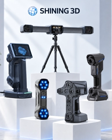
Scan the part — Shining 3D FreeScan, OptimScan or AutoScan captures the surface.
Align to CAD — the scan is aligned to the reference model or a golden sample.
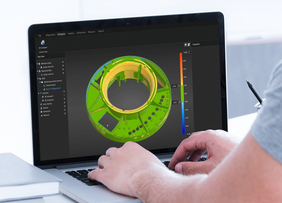
3D compare — software computes the deviation at every measured point.
Analyse — GD&T evaluation, cross-sections and deformation analysis.
Report — colour maps and pass/fail analysis, exported automatically.
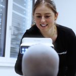
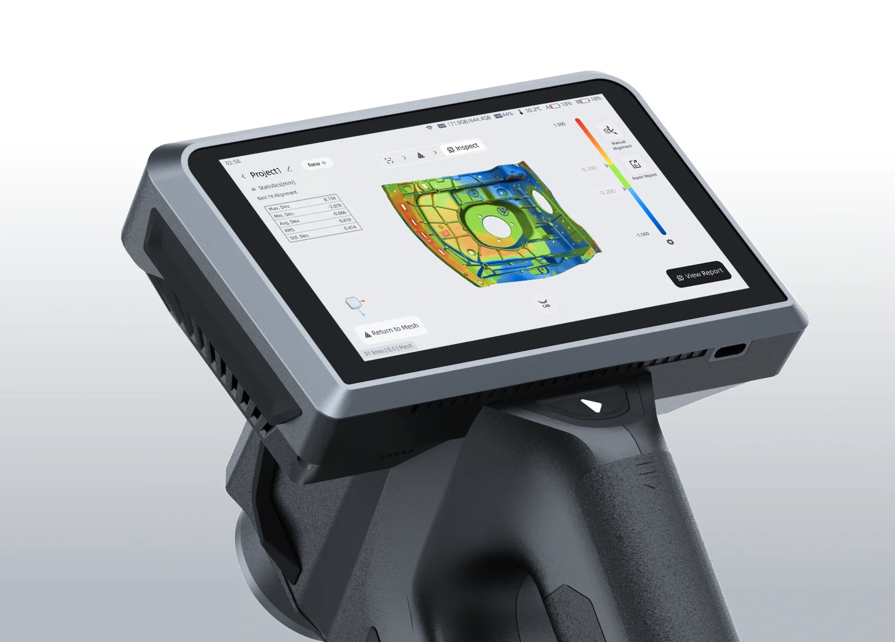
The result on the device itself: max, min and RMS deviation against the CAD, before anything leaves the shop floor
What 3D inspection can verify
CAD comparison and colour deviation maps — see exactly where and how much a part deviates.
GD&T (geometric dimensioning and tolerancing) — verify flatness, position, profile and more.
Profile and surface analysis — check complex freeform and curved surfaces.
Cross-section and deformation analysis — inspect internal geometry and detect warpage.
Automated inspection reports — repeatable, shareable documentation for customers and auditors.
3D scanner vs CMM — complementary, not competing
A common question is whether a 3D scanner can replace a coordinate measuring machine (CMM). In practice the two technologies complement each other. A CMM excels at probing specific critical features in a controlled environment, while a 3D scanner captures the whole part quickly and analyses many dimensions from a single scan. Many manufacturers use both: the scanner for rapid full-surface inspection and to identify areas of interest, and the CMM to confirm specific critical features when required.
Catch problems earlier to reduce scrap and rework
Quality control creates the most value when it catches problems before they propagate. If dimensional drift develops gradually in a machining, casting or stamping process, inspecting only the finished part may reveal the fault after a whole batch is already produced. With 3D scanning you can move inspection earlier — scan in-process, detect the deviation, correct the process and continue — reducing defective material, rework and downtime.
Our 3D inspection and metrology solution
3D scanners — metrology-grade Shining 3D systems with standards-traceable accuracy.
Automotive — prototype validation to final assembly verification of body panels, powertrain and trim.
Aerospace — turbine blades and structural components where small deviations affect performance and safety.
Manufacturing, tooling and energy — any application that must verify complex geometry and maintain dimensional control.
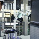
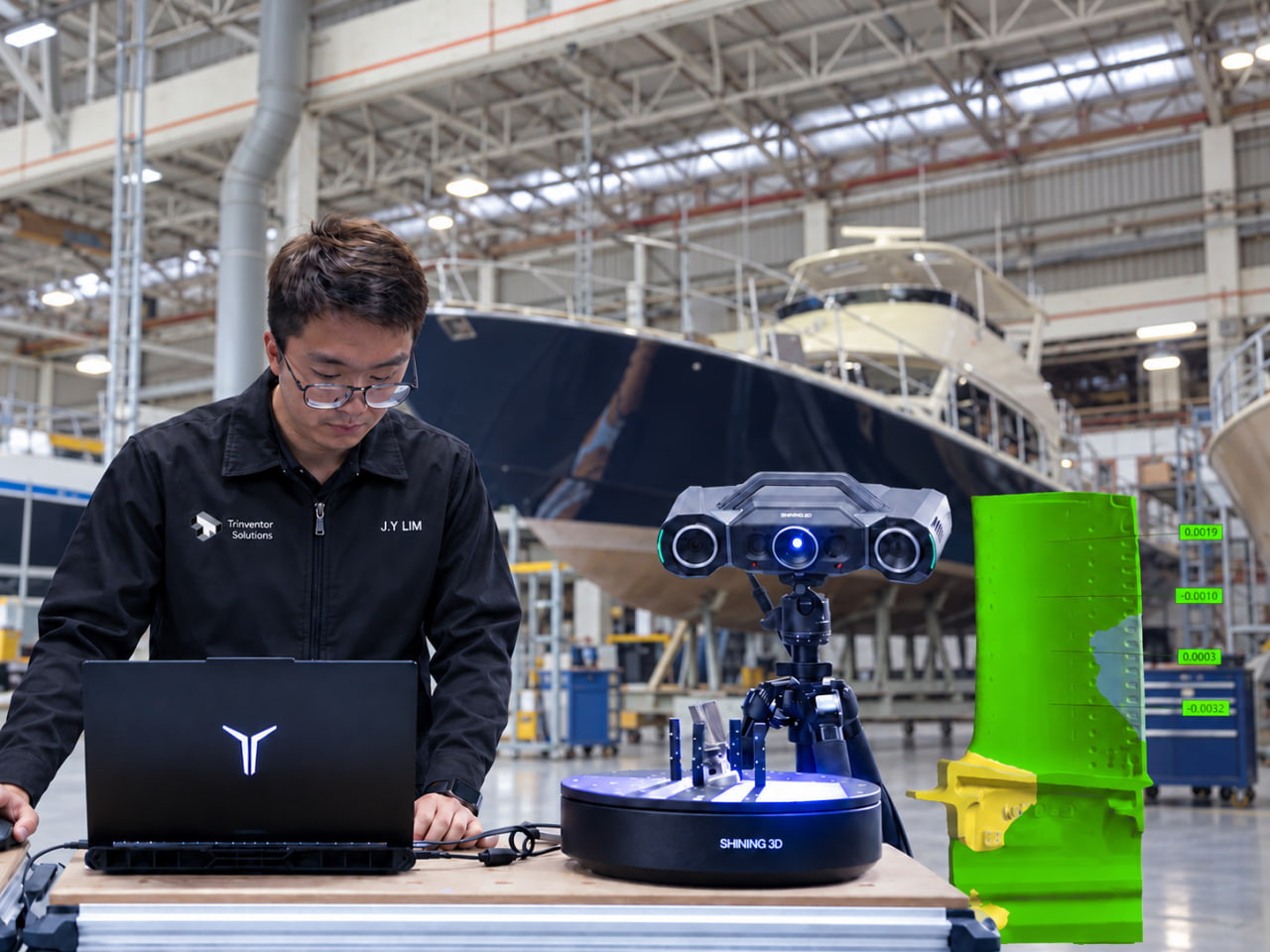
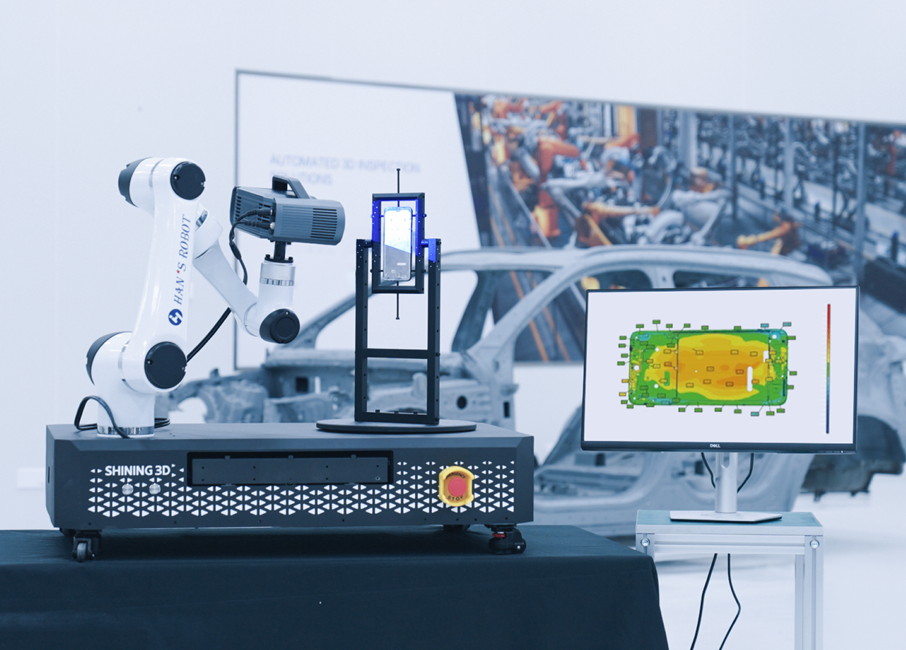
At volume the cell does the measuring — robot, turntable and a deviation map the operator only has to read
First-article and incoming inspection
The same inspection principle covers both jobs: prove the first part off a tool, and check what arrives at goods-in. What changes is the machine, because the size of the part and how often you measure it decide which one is sensible.
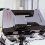
Optical tracking removes the set-up, and the part stays where it is
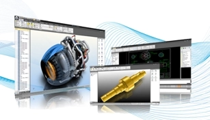
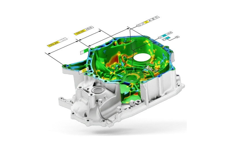
Reference against measured: alignment, best fit and the deviation map, all in the inspection softwareThe report someone signs: deviations mapped across the part and the tolerances called out where they matter
A report that stands up
The difference between a scan and an inspection is the paper behind it:
Alignment to datums, not to the nicest-fitting surface — the alignment is where most disputes are won or lost.
Callouts against the drawing, with the tolerance you are claiming and the uncertainty you are claiming it to.
Colour-mapped deviation so the person reading it can see where the part went wrong, not just that it did.
Traceability — the scan, the alignment and the report kept together, because a report nobody can reproduce is an opinion.
The software side of this is covered on the inspection pages and in the scanner vs CMM comparison for the cases where a contact measurement is still the right answer.
What a first setup really involves
Budget for the unglamorous parts: a stable place to put the part, fixturing that repeats, surface preparation (matte spray on shiny parts, markers where the geometry is featureless), a calibration artefact, and one rehearsal on a part you already know the answer for. Teams that rehearse once spend their time inspecting; teams that do not spend it arguing about the scanner.
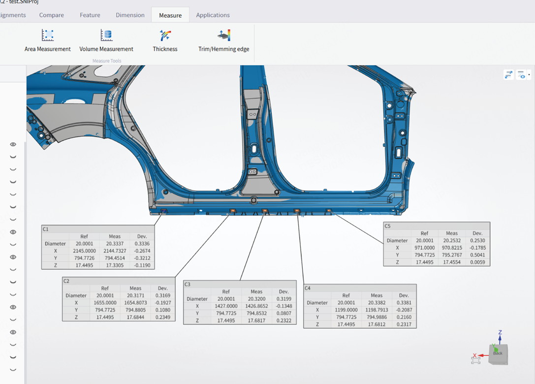
Measured against nominal for every feature — the table an auditor asks for
Frequently asked questions
What does first-article inspection with a 3D scanner involve?
The part is scanned, aligned to the CAD model, and the software computes the deviation at every measured point — then reports it as a colour map with the out-of-tolerance areas called out. Compared with sampling points with hand tools, the difference is that you see deviation across the whole surface, not only where you remembered to measure.
Can a 3D scanner replace a CMM?
For full-field surface inspection it does a job a CMM cannot do economically, and it is the reason most quality departments now run both. Where a drawing has tight dimensional and geometric tolerances on simple features, a touch probe or CMM remains a valid instrument — and the FreeScan Trak Pro2 can add contact probing to the same scanning workflow, so the two are not mutually exclusive.
What tolerances can you actually report against?
The machine sets the floor: 0.01 mm class on the AutoScan Inspec2 desktop, 0.005 mm class on the OptimScan Q12, and 0.02 mm on the FreeScan metrology handhelds — with acceptance testing to ISO 10360 or VDI/VDE 2634 Part 3 in an accredited laboratory, which is what supports a traceable report.
Do I need inspection software as well as a scanner?
Yes — the scanner produces geometry and the software produces the verdict. We supply them together, configured as a package, because the reporting your quality system needs decides which software you should run.
What does an inspection setup cost in Malaysia?
Quoted as a system: scanner, software, calibration documentation and the training to run it. Tell us the parts, the tolerance you must prove and who the report goes to, and we will specify against that.
Acceptance testing to ISO 10360, the certificate that comes with the instrument, and calibration you can show an auditor. The accuracy guide explains what a metrology acceptance test proves that a marketing accuracy figure does not.
What do I need to start inspecting?
Three answers: the size of the parts, the tolerance you have to prove, and who reads the report. From those we specify the instrument, the software and the fixturing — and we will say plainly if your tolerance is not a scanning job at all.
Talk to our team
Tell us your project and we will match a scanner and software combination to your budget, materials and accuracy requirement. Contact Trinventor Solution for a live demo, consultation and local after-sales support in Malaysia.