3D Scanning Quality Control: A Practical Guide for Manufacturers
3D Scanning Quality Control: A Practical Guide for Manufacturers
Quick verdict: A calliper tells you what happened at the points you touched. A metrology-grade 3D scanner captures the whole surface, compares it against CAD and produces an auditable deviation report in hours rather than days. If your risks live in warped flanges, worn tooling or freeform profiles, full-surface inspection finds them before your customer does.
Measure five points on a machined bracket and you know what happened at five points. The warp in the middle, the taper along the flange, the bow that only appears after the clamps come off: none of it shows up in a calliper reading. Those blind spots are where field failures are born.
3D scanning quality control asks a different question. Instead of sampling dimensions one at a time, it captures the full surface of the part as a dense point cloud, aligns that data to the CAD model and reports deviation everywhere at once. This guide covers how the method works, how it compares with touch probing and CMMs, what inspection software does with the data, where it fits on a production line, and what accuracy you can reasonably expect in a Malaysian workshop.
What 3D scanning quality control actually measures
The principle is simple. Measurement energy, normally a blue laser line or a structured light pattern, is projected onto the part surface. Sensors watch how that pattern distorts and convert the distortion into coordinates. One pass captures millions of points; the software stitches the passes together into a mesh that represents the part as it physically is.
That mesh then has to be placed in the same coordinate system as the design. A metrology-grade 3D scanner has no idea where the part was meant to sit, so the inspection software applies a best-fit alignment, or a datum-based alignment tied to the drawing, to line the scan up with the CAD geometry. Once both occupy the same space, every point on the mesh has a corresponding point on the CAD surface, and the gap between them is the deviation.
What comes out is a colour-coded deviation map. Green sits inside tolerance, red shows material above nominal, blue shows material below. The map is only the visible layer. The same data drives dimension tables, GD&T callouts and pass/fail verdicts, so the report covers features nobody thought to measure by hand.
3D scanning compared with touch probing and CMMs
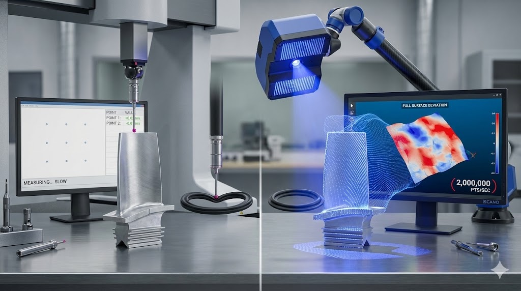
A touch-probe coordinate measuring machine remains an excellent instrument. It is traceable, it is repeatable, and for a bored hole with a tolerance measured in a few microns it is still the reference method. Optical scanning does not replace that measurement. It answers the much larger question of how the entire surface behaves.
The distinction matters because a CMM measures what its probe can reach, one point at a time. Freeform geometry, thin-wall plastic parts and soft components each expose a weakness: either the probe cannot describe the shape economically, or clamping the part distorts what you are trying to measure.
Capability
Touch-probe CMM
3D laser scanning
Data capture rate
Roughly one point per second
Up to 2 million points per second
Coverage
Discrete sample points
Full surface, every point
Deformation risk
Present on soft or flexible parts
None, contact is optical
Complex geometry
Demanding on organic shapes
Handles intricate forms directly
First article cycle time
Days, including programming
Hours
Digital record
Measurement logs for checked points
Complete point cloud archive
Many shops end up running both. A portable scanner handles incoming parts, freeform surfaces and tooling wear, while the CMM is wheeled out for the handful of tight prismatic dimensions that justify the fixturing and programming effort. An articulated arm fitted with a laser head sits between the two, letting you probe and scan on one platform.
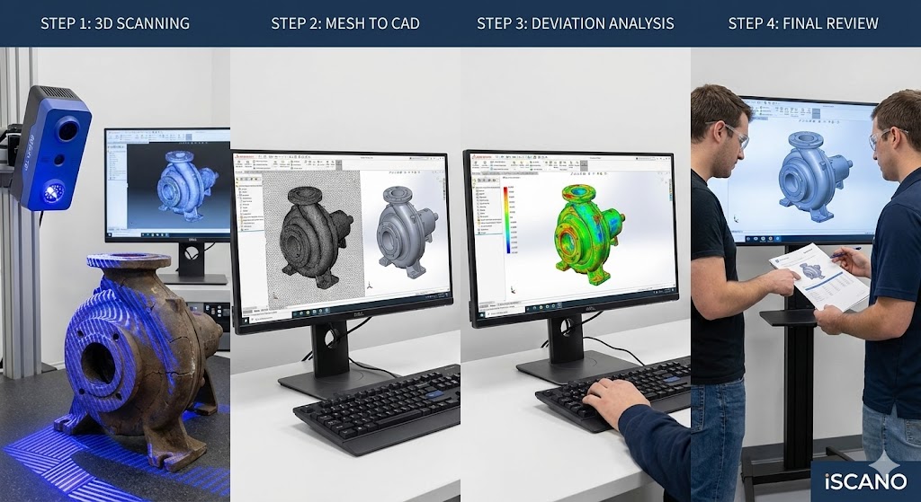
The inspection workflow: scan, align, compare, report
A metrology-grade workflow has four stages, and the discipline of the first two determines the credibility of everything after.
Scan. The operator captures the part with a portable or handheld scanner, working around the geometry until every surface of interest is covered. Multiple passes are stitched automatically, either by tracking features on the part or by tracking targets and reference markers.
Align. The point cloud or mesh is imported into inspection software, which positions it against the original CAD with a best-fit routine, or with a datum alignment that mirrors the drawing. Alignment choice is a quality decision, not a formality: a loose best-fit on a warped part can hide the very distortion you are looking for.
Compare. The software computes deviation across the whole surface, generates the colour map, and builds dimension tables for each critical feature. GD&T checks such as profile of a surface, flatness, true position and concentricity are evaluated against the full surface rather than a few sampled points.
Report. An inspection report is exported for QA sign-off, typically a PDF with pass/fail tables, annotated colour maps and measured values against nominal. For traceability, the raw point cloud is archived alongside it.
Work that used to consume days of CMM programming and measurement now finishes in hours. On a new tooling release that difference decides how quickly the line is cleared for volume production.
Inspection software: what the different types do
Hardware gets the attention, but the software decides how usable the inspection result is. Most metrology setups combine three layers.
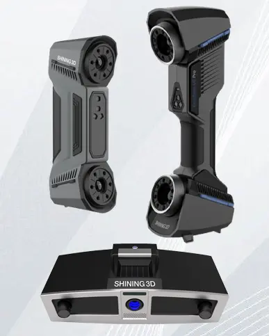
Scanner control software. Comes with the device. It drives exposure, handles mesh cleanup, filters noise and stitches scan passes into a single watertight model. Shining 3D supplies this layer with its scanners.
Full deviation and inspection packages. This is where the analysis happens. Geomagic Control X, part of the Hexagon metrology family, imports CAD and scan data side by side, performs the alignment, produces full-field deviation maps and dimension tables, verifies GD&T callouts, and generates templated reports that repeat the same way every time.
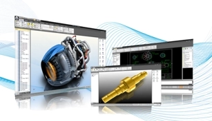
CAD-integrated metrology and reconstruction. Where the job moves from checking to correcting, CAD software such as ZW3D lets engineers compare on the model, repair surfaces, and rebuild scanned mesh into editable parametric geometry. Results move out as STEP, IGES or mesh files, so they open in whatever platform the design team already runs.
Standards matter at this layer too. GD&T definitions are read against the drawing conventions the shop uses, and metrology-grade scanners themselves are verified to VDI/VDE 2634, the guideline that describes how optical measurement systems are tested for accuracy. Buy a scanner with no stated conformity and you have a digital model, not an inspection result.
Reading a deviation map without fooling yourself
A deviation map is persuasive, which is exactly why it deserves scepticism. Red does not automatically mean scrap. It means the surface sits outside the tolerance band you told the software to apply, at the scale you chose. Open the scale too far and everything looks green. Weight the alignment towards a datum that already moved and the real problem disappears into the fit.
Two habits keep the report honest. Set the deviation limits from the drawing tolerance before you look at the result, and keep the alignment method in the report so a reviewer can see how the part was positioned. A colour map with an unstated alignment is an opinion, not evidence.
Where it fits in production
First article inspection
First article inspection exists to prove, feature by feature, that the first part out of a new or modified tool matches the drawing, and it is frequently the biggest bottleneck between tooling sign-off and volume output. Scanning collapses the cycle: capture the full geometry in minutes, compare it against CAD automatically, and hand quality a Go or No-Go verdict with annotated deviation data attached. The team no longer has to choose which dimensions to check, which removes the argument about what the first article actually proved.
In-process checks and trend monitoring
Instead of an annual dimensional audit, sample parts at a fixed interval and scan them. Each scan adds a data point to a wear curve for the tool or process, and deviation growth becomes visible before parts drift out of tolerance. Moulds, stamping dies and forming tools all behave this way, and the trend tells you when to schedule maintenance rather than when to sort scrap. On a flexible line, an industrial handheld 3D scanner can be taken to the machine instead of the part being carried to a metrology room.
Incoming inspection and supplier verification
Received parts are the hardest to argue about, because the measurement conversation happens across two companies. A full-surface scan settles it with a file. Verification against the supplied CAD, rather than a certificate of conformance, gives you evidence about the parts in your rack today, and the archived point cloud is there months later if the same lot fails in the field.
Tooling and mould verification
Tooling wears progressively and quietly. Scanning at commissioning establishes a baseline, follow-up scans show exactly where material has moved, and repair decisions get made from measurement instead of instinct. This is also the stage where repairing a tool becomes practical: a scan of the worn surface gives a machinist the true geometry to work back from.
Reverse engineering legacy parts
Plants are full of equipment whose drawings left with someone who retired. When a casting cracks or an imported spare becomes unobtainable, a scan of the surviving part yields a high-resolution mesh that engineers can rebuild into editable parametric CAD. The workflow is covered in more detail under our reverse engineering solution, and it is often the difference between a two-week repair and a two-month wait for a part from overseas.
Tolerances and accuracy expectations
Metrology-grade scanners are typically quoted at 0.025 mm, or 25 microns, with that figure certified against a guideline such as VDI/VDE 2634. Use that number as a ceiling on what the instrument can do, not a promise about the result on your bench. For most aerospace and automotive work, sub-50-micron results are achievable with calibrated equipment and a sensible setup.
Several factors push the real figure wider:
Scanner type and working volume. Higher resolution over a small field does not automatically carry over to a large one. Volumetric accuracy across a big part is always looser than accuracy over a small area.
Part surface. Blue laser and structured light systems cope well with semi-gloss, painted and dark finishes. Polished chrome and mirror finishes usually need a temporary matte coating so the sensor sees diffuse light instead of a reflection.
Geometry and accessibility. Deep pockets, internal channels and re-entrant features can shadow the sensor. No amount of software fixes a surface that was never captured.
Environment. Vibration, draughts and temperature swings all move the part or the instrument during capture. Portable systems are built to tolerate a shop floor, but not a machine that is running beside them.
Alignment choice. Datum alignment reproduces how the part functions in assembly. Best-fit alignment shows overall form. They answer different questions, and mixing them up flatters or penalises a part for the wrong reason.
One discipline ties these together. Measurement uncertainty should be a small fraction of the tolerance you are judging, and many quality systems ask for roughly a tenth so that the gauge itself never becomes the dominant source of error. If a feature is toleranced tighter than your scanner can reliably resolve, that feature belongs on a touch probe.
Industries where it pays off
Aerospace
Turbine blades, structural brackets and nacelle hardware are checked against tight tolerances where hidden deformation from heat stress, material variation or machining drift is the real risk. Full-surface deviation analysis surfaces that class of defect, and the as-built geometry can be archived for lifecycle compliance documentation.
Automotive and EV suppliers
Suppliers work to IATF 16949 quality systems while being pushed to shorten inspection cycles. Scanning covers fast first article approval for new tooling and in-line checks on powertrain, chassis and body-in-white components. Virtual assembly is the newer use: scan two mating parts, fit them together digitally, and settle a fitment problem before anyone cuts metal.
Industrial machinery, moulding and die casting
Injection moulders, die casters and precision machinists use scanning to track tooling wear across long production runs. A wear baseline plus regular sample scans removes the guesswork from maintenance scheduling, and the scrap events that follow an overrun tool tend to disappear with it.
Medical devices and precision engineering
For medical device manufacturers and precision component suppliers, dimensional compliance is a regulatory matter as much as a technical one. Metrology-grade scanning produces the audit-ready digital records that FDA, CE and ISO 13485 quality systems expect, and its resolution supports components with sub-millimetre tolerances. Malaysian mould and die, E&E and medical device manufacturers face the same customer audits as their regional competitors, and the documentation requirement is the part that most often catches teams out.
Frequently asked questions
What accuracy should you expect from a 3D scanner in quality control?
A metrology-grade instrument is normally specified at 0.025 mm, which is 25 microns, verified against a guideline such as VDI/VDE 2634. The achievable figure on your part depends on the scanner type, the geometry, the surface finish and the environment. Sub-50-micron results are realistic for most aerospace and automotive work with properly calibrated equipment.
Does 3D scanning cope with reflective or dark surfaces?
Blue laser and structured light systems work well on semi-gloss, painted and dark finishes. Highly reflective chrome surfaces may need a temporary matte coating to remove the mirror effect. Some newer systems handle such surfaces without preparation, but it is worth testing on your actual material before you commit.
What file formats does inspection software use?
Inspection results usually leave as PDF reports containing colour deviation maps and dimension tables. For reverse engineering and CAD reconstruction, the common interchange formats are STEP and IGES, which open in the mainstream design platforms. The raw scan is normally archived as a point cloud or mesh alongside the report.
Is 3D scanning practical in a shop floor environment?
Portable metrology scanners and articulated arms are designed for shop floor use, with compensation for the vibration and temperature variation found there. Lab-grade CT scanning still needs controlled conditions. A portable laser scanner can be set up next to the production line for in-process checks, provided it is not fighting a running machine for stability.
Will a scanner replace our CMM?
Usually not, and it is rarely the right goal. Scanning takes over the full-surface work that a CMM cannot do economically, which tends to free the CMM for the tight prismatic dimensions it measures best. Most shops that adopt scanning keep probing for the features that need it.