Automated Quality Inspection with a Robot and a 3D Scanner
Automated Quality Inspection with a Robot and a 3D Scanner
Quick verdict: a robot and a 3D scanner together turn inspection from an appointment into a process step. The robot provides the one thing manual scanning cannot — the same part, in the same pose, every single cycle — and the scanner turns that repeatability into data that compares cleanly against CAD. Automate the scan when parts are measured at volume, when the measurement must keep up with production, or when the same dimension must be checked the same way on every shift.
Manual 3D scanning is a skilled, flexible craft: an engineer holds the scanner, watches the coverage live, adapts to tricky geometry and produces a report. Its limit is arithmetic — one person, one scanner, one part at a time. When production volume rises, inspection either lags behind or degrades into sampling: a few parts measured well, everything else assumed. That assumption is exactly what automated inspection removes.
This article covers how robot-based automated inspection actually works in a factory — the architectures, where the accuracy comes from, what data you get, and the honest limits. For the commercial picture and how we build these cells in Malaysia, see the dedicated automated 3D inspection solution.
Why a robot in the measurement loop at all
Three properties of robots make them good at inspection:
They repeat poses. Scanning is comparative: every deviation map is only as trustworthy as the pose the part was scanned in. An arm returns to the same position and orientation within its repeatability, so scan after scan is directly comparable — across the shift, the month and the operator.
They never get bored. The thousandth part today gets the same care as the first. That is what makes 100 % inspection of critical features an actual plan rather than a slogan.
They are already there. Where a cobot loads a machine (see CNC machine tending), the arm that just unloaded the part is a natural candidate to also hand it to a scanner. The increment is a scanner station, not a second robot.
The features that matter decide the instrument: board-level checks and machined tolerances use different scanning systems.
The three architectures of automated inspection
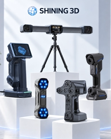
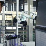
The robot carries the scanner. The arm moves a metrology scanner around the part — usually on a turntable — covering the surfaces in planned passes. Geometry too large to move (big castings, welded structures, moulds) is scanned in place; the scanner goes to the part, not the other way around. Shining 3D’s RobotScan series is a packaged version of exactly this arrangement — scanner, cobot, controls and software specified as one system.
The robot presents the part to a fixed scanner. The most throughput-efficient shape for small and medium parts: the arm lifts the part from the line, presents it to a scanner at one or more programmed angles, and returns it. The scan itself can be seconds long, so the station can keep pace with production. This architecture suits parts that are awkward to hold steady by hand but easy to hold in a gripper.
The robot loads a metrology station. An existing scanner or CMM becomes the measurement instrument, and the robot becomes its feeder. Nothing about your reference measurement changes — it just stops waiting for someone to load it, and starts running across shifts. This is often the lowest-risk first project: the robot’s job is handling, which is the part of the process that has no opinion about tolerances.
Where the accuracy comes from
A common misconception is that robot-mounted scanning is “less accurate” because a robot is involved. The measurement accuracy of a scan comes from the scanner and the calibration of the scanning process, not from the arm’s positioning accuracy alone:
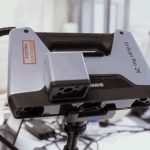
The scanner sets the measurement quality — its optics, its field accuracy, and whether it is a metrology-grade instrument with acceptance testing (the inspection and metrology solution covers how scanners are specified and accepted).
System calibration ties the robot and scanner together. A RobotScan-type cell is calibrated as a scanning system: the scanner’s position is known in the robot’s coordinate frame, so scan data from many robot positions merges into one accurate point cloud. The robot’s repeatability makes each pass reproducible; the scanner and the calibration provide the accuracy.
The task decides the instrument. Scanning a bracket’s mounting holes to a tenth of a millimetre and scanning a 2 m frame for overall flatness use different scanners, different fixturing and different expectations. Honest specification starts from the tolerance on your drawing, not from a demo part chosen for the photo.
What the cell needs to work — the unglamorous list
Automated inspection projects succeed or fail on details that are not in the scanner’s brochure:
A presentation the robot can repeat. The part must arrive where the gripper expects it, every time: trays, fixtures, or a conveyor stop. A robot holding a part has its own repeatability story; a robot picking scatter-fed parts is an automation project of its own.
Surface handling. Shiny machined surfaces and dark plastics scan differently from matte castings. Where a coating spray is needed for reliable optical capture, the cell can fold it into the routine — automated or manual depending on the part.
Cleanliness. Swarf, coolant and finger grease all show up in scan data as noise. Parts coming straight out of a machine want a blow-off before measurement.
Light and vibration. Shop-floor scanning tolerates daylight and forklifts better than workshop folklore suggests — but heavy hammering next door is still the cell’s problem, and cell placement accounts for it.
Data handling. The output of automated inspection is not a report on the last part — it is a stream: every scan compared to CAD, results stored, trends visible. Decide where that data lives (file server, QMS, MES) before the cell is built, not after. Modern RobotScan-class systems support this integration by design.
When automating the scan is worth it
Automate when
The same features are checked on many parts
Measurement must keep up with the takt
Every part or dense samples need proof
Data across shifts must be comparable
The part is already handled by a robot
Stay manual when
One-off parts and prototype work
Only a handful of parts per month
The scanning job changes shape daily
The tolerance belongs on a CMM anyway
Hybrid — the common answer
Automated cell for volume and daily proof
Manual scanning for first articles and odd jobs
Both feeding the same quality system
A worked picture: first-off in a machining cell
A practical arrangement that shows all the moving parts. A cobot tends a CNC lathe. At every tool change and at each first-off, the arm that was already unloading the machine carries the first part to a scanner station instead of the outfeed tray. The scan compares the part to CAD; the deviation map and key dimensions land in the quality system; the operator sees a pass/fail on a screen within the cycle it was taken. Production continues on the verified setting instead of on the assumption that the first part looked right. Nothing about the machining changed — but the gap between making a bad part and knowing about it shrank from the next quality visit to the next cycle.
Where the cell also runs automated metrology at a higher level — larger parts, on-arm scanning — the same building blocks scale up; the differences are the scanner class, the fixturing and the scan plan. The scanner range page shows how the instrument tiers map to what is being measured.
Honest limits
Not a CMM replacement. The tightest tolerances — where uncertainty budgets run below what optical scanning can hold — stay with contact metrology. Automated scanner cells cover volume and speed; the CMM covers the last word.
Fixturing is the hidden cost. Every part needs a way to be presented, held and (where necessary) coated. Cells that skip this planning re-invent it painfully later.
Setup variety sets the ceiling. A cell built for one part family flies; a cell that must scan twenty radically different parts needs its own scan-planning discipline. That is a design choice, made early.
Scaling the part, not the ambition. Panels and small castings are friendly; three-metre welded frames want a different architecture (often scanner-on-arm with the cell built around the workpiece).
Frequently asked questions
Do I need a robot to automate 3D inspection? Not always. A fixed scanner with a turntable automates plenty of parts without any arm. The robot earns its place when parts must be handled — picked from production, presented at multiple angles, or loaded into an existing station — or when the scanner must travel to a part too large to move.
Does robot-mounted scanning lose accuracy compared to a fixed setup? No, when it is done as a system. The accuracy comes from the scanner and the calibration of the robot-scanner arrangement, with the arm’s repeatability providing the reproducible pose. A properly calibrated on-arm cell and a fixed cell differ in what they can reach and how fast they cycle, not in whether robot motion makes the measurement unreliable.
What parts suit automated scanning best? Small and medium parts checked in series are ideal: castings, machined brackets, connector bodies, stamped components. Parts with matte or cast surfaces scan most easily; shiny and black surfaces are handled with practice and, where needed, coating. The hardest cases are not the material — they are parts with no repeatable way to be presented.
How do I start without a big project? Start with the part you already measure most often and the tolerance you trust. Run it at the demo stage: scan the actual part in the actual arrangement, review the data against your drawing, and let the numbers set the size of the project. That is the order we work in for every cell — see the automated inspection solution for how it runs in Malaysia.