Laser Marking for Electronics and PCB: Identification Without Melting the Part
Laser Marking for Electronics and PCB: Identification Without Melting the Part
Quick verdict: Heat is the enemy of electronics marking, which is why UV is the answer: it marks plastic and PCB cold, without melting or burning the component.
Electronic components are small, heat-sensitive and need permanent identification — a combination that rules out most marking methods. Labels peel, ink smudges, and a hot laser can melt the very plastic you are trying to mark.
That is why electronics marking is a specific skill: cold UV laser marking for plastic, PCB and coatings, plus fiber for metal parts. Get the choice wrong and you either damage the component or produce a mark that fails inspection a week later.
Why laser for electronics
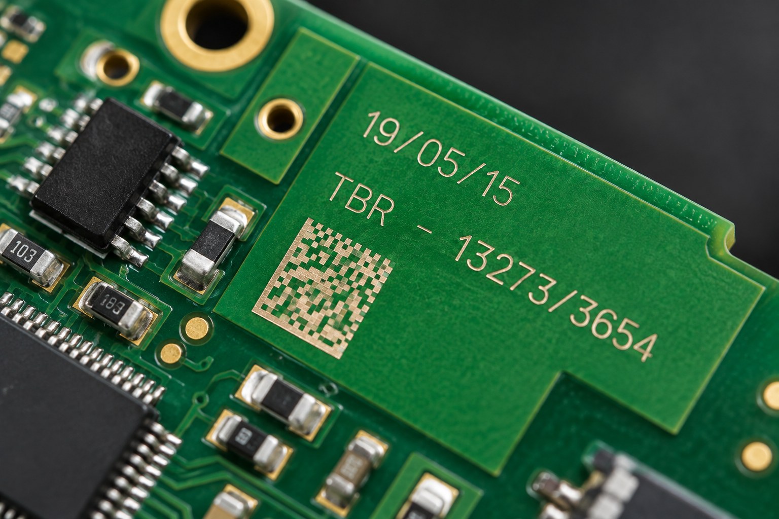
Cold marking — UV marks plastic and PCB without heat, so nothing melts, warps or discolours.
Permanent — serial numbers and QR codes that do not fade, smear or rub off in handling.
Fine — legible codes on components only a few millimetres wide.
Non-contact — no pressure on delicate boards, and no consumables to replace.
Variable data — every part can carry a different serial number or QR code without a new tool or stencil.
The alternative — printed labels — fails exactly where electronics are used: heat cycles, solvents, cleaning and abrasion. A laser mark becomes part of the surface rather than sitting on top of it.
What gets marked
Item
Mark
Laser
PCB boards
Board IDs, QR codes, revision marks
UV
Plastic enclosures
Serial numbers, logos, ratings
UV
Buttons, switches, keycaps
Icons, text, backlight windows
UV
Coated metal housings
Labels, part numbers
UV (through coating) or fiber
Metal connectors and terminals
Part numbers, batch codes
Fiber
Cable jackets and sleeves
Markings, length, batch
UV
Barcode and QR labels
Data matrix codes
UV
Most of an electronics bill of materials is not metal, and that is the point: the majority of these parts are marked by UV rather than fiber.
Why heat matters (and why UV is the fix)
The UV beam reacts with the surface rather than heating it, so enclosures and boards are marked without melting or discolouration
A standard fiber laser marks plastic by heating it. On a thin enclosure or a populated board, that heat can melt, warp, bubble the solder mask or discolour the part — and the damage is not always visible immediately.
A UV laser works differently. Its 355 nm wavelength breaks molecular bonds on the surface directly rather than burning through it, so the material never gets hot enough to deform. The result is a clean, high-contrast mark on materials that a fiber or CO2 laser would ruin.
This is called cold marking, and it is the single reason UV exists in electronics work.
UV, fiber and CO2: which laser for which part
Laser
Wavelength
Good for
Avoid on
UV
355 nm
Plastics, PCB, coatings, anodised and painted surfaces, cable jackets
Thin plastics and populated boards — too much heat
CO2
10.6 µm
Bare wood, acrylic, glass, some organics
Metals — they reflect it; also unsuitable for most engineering plastics
If you mark only one material family, the choice is easy. If you mark both plastic housings and metal connectors — which most electronics manufacturers do — you need either two machines or a machine that covers both.
The right machine
Machine
Fit for electronics work
xTool F2 Ultra UV
5W 355 nm UV source. Cold marking on plastic, PCB, coatings and heat-sensitive components — no melting, no burn, no solder-mask damage
xTool F2 Ultra
60W MOPA fiber plus a 40W diode source. Fiber covers metal connectors, housings and aluminium; the diode handles engraving on organics
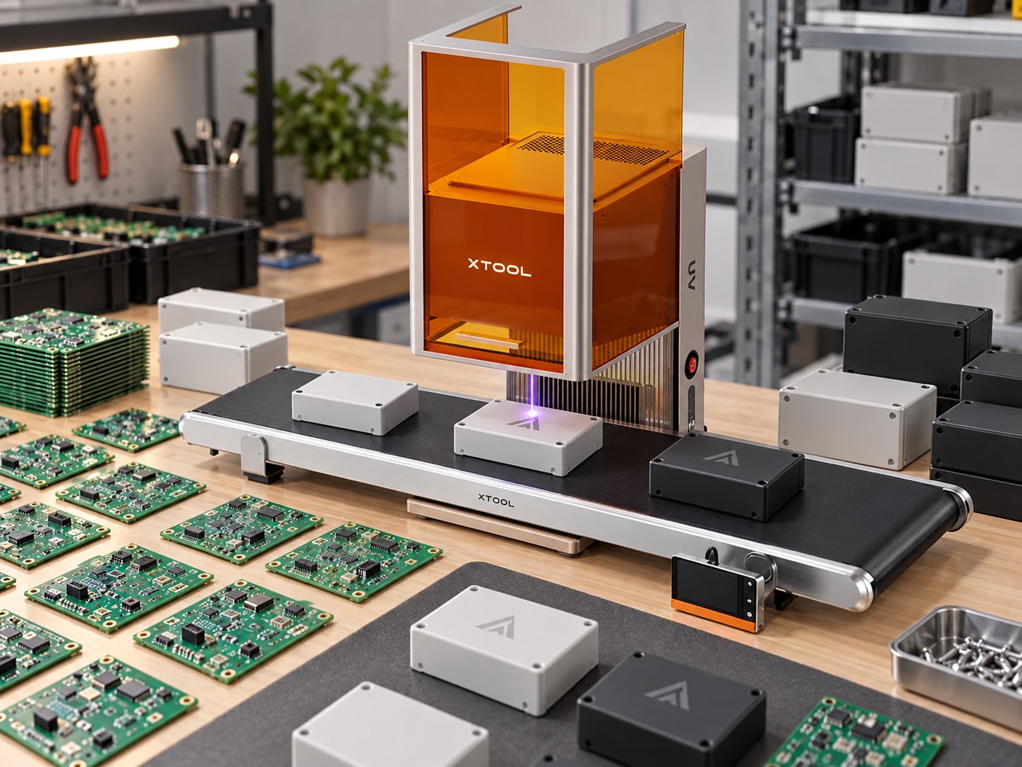
For most electronics work the F2 Ultra UV is the answer, because most of what needs marking is plastic or board. Where the workflow also includes metal connectors and machined housings, the F2 Ultra covers those with its fiber source.
Both are enclosed machines with a work area suited to batch marking of small parts. A rotary attachment for cylindrical work such as cable sleeves and round connectors is available separately.
Contrast and legibility: what makes a mark readable
A mark that looks fine under the machine light can fail under a scanner. Three things determine whether it works in production:
Contrast — the mark must differ enough from the surrounding surface for a camera. On dark plastics, UV often produces a light mark; on light plastics a dark one. The chemistry of the specific polymer decides this, which is why testing matters.
Cell size — a QR or data matrix code needs enough pixels per cell for the scanner. Smaller fields of view mean more cells per millimetre, and a code that is too dense will not read reliably on a handheld scanner.
Angle and finish — glossy surfaces reflect scanner illumination back at the reader. Matte finishes read more consistently, which is one reason marks on textured enclosures often outperform marks on polished ones.
A mark is not decoration. If a scanner cannot read it on the line, it has failed regardless of how it looks.
Marking on PCB: what the board can take
Boards are the most demanding substrate in this workflow, because the mark has to sit alongside components that can be damaged and a solder mask that can be discoloured.
Mark in the panel margin or a keep-out area wherever possible, rather than beside a populated component.
Stay off the solder mask if the mark needs to survive reflow — marking before assembly behaves differently from marking after.
Bare copper and gold finishes mark differently from each other and from HASL. Test the actual finish you use.
Conformal coating changes the surface entirely. If you coat after marking, confirm the mark still reads; if you mark after coating, confirm the laser does not penetrate it.
Fixtures, positioning and repeatability
Marking one part well is a demonstration. Marking ten thousand identically is a production process, and the difference is fixturing.
A simple plate with locating pins or a machined pocket holds a board or enclosure in the same position for every cycle, so the mark lands in the same place without an operator aligning it by eye. That matters in two ways: the mark is consistent, and the cycle time drops because nobody is adjusting anything.
For small parts, mark a batch on a single plate rather than one at a time. For cylindrical parts such as cable sleeves and connectors, a rotary attachment lets the machine mark around the circumference rather than only on the flat.
Common problems and fixes
Problem
Likely cause
Fix
Smeared or low-contrast mark on plastic
Wrong wavelength — too much heat, not enough surface reaction
Switch to UV; reduce power and increase passes
Mark reads at the desk but fails on the line
Code too dense, or glossy surface reflecting scanner light
Increase mark size, reduce cell count, or change the surface finish
Solder mask discoloured around the mark
Heat-affected zone extending past the intended area
Move the mark to a margin, lower power, or use UV
Inconsistent position part to part
No fixture — operator alignment by eye
Add a locating plate or pocket
Mark disappears after cleaning
Marking only the coating, not the substrate
Increase depth slightly, or mark the substrate under a clear coat
Metal connector mark too shallow
Fiber power or frequency not matched to the alloy
Adjust MOPA settings for the specific material; test coupons first
Frequently asked questions
Will a UV laser damage the components on a populated board? UV marking is a surface reaction and the heat-affected zone is minimal, which is exactly why it is used on populated boards. Keep the mark away from exposed wire bonds and test on a scrap board first.
Can one machine mark both plastic and metal? Not ideally — the wavelengths differ. UV is the correct choice for plastic and PCB, fiber for metal. Where both are needed, plan for two sources or two machines.
Can the mark survive sterilization and repeated cleaning? On plastic and metal, a properly set laser mark is part of the surface and survives alcohol, most solvents and repeated handling. Aggressive solvents on some plastics will still affect it, so test with the exact cleaning agent you use.
How small can the text be? Fine enough for component-scale marking, but legibility sets the practical floor: if a human or a scanner cannot read it, the size is too small regardless of what the machine can produce.
Do I need a rotary attachment? Only for cylindrical parts — cable sleeves, round connectors, tubes. It is an optional accessory, not required for flat boards and enclosures.
The only way to know how a mark looks on your enclosure or board is to test it. Send us a sample part and we will mark it — you will see the contrast, the legibility and whether it survives your handling, before you commit to anything.
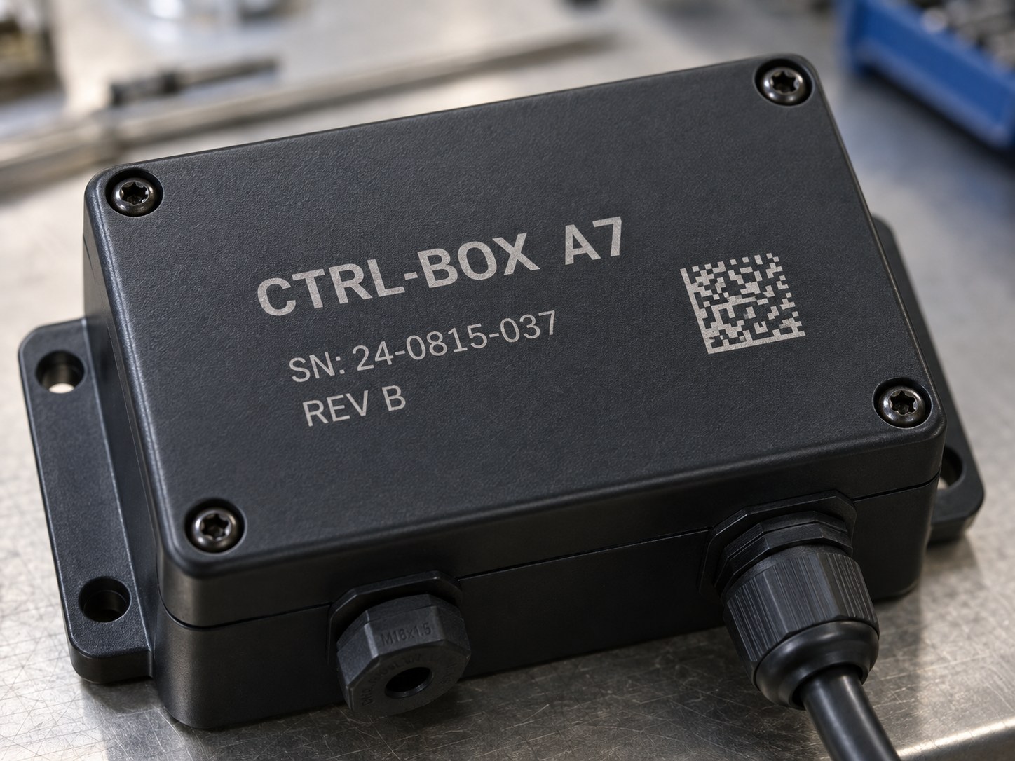
What the finished mark looks like on textured black plastic: high contrast, and fine enough to carry a serial number and a QR code
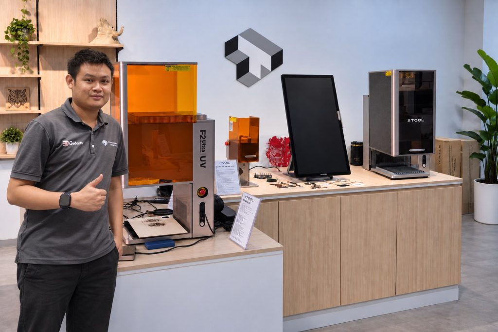
Our Kuala Lumpur showroom. Bring your product and we will engrave it in front of you, so you see the real result before you buy.
Laser engraving is easiest to judge in person. Tell us what you want to mark and bring a sample to the showroom, or send us a photo and we will tell you which machine and power fits the job.