3D Printing for Architecture, Construction and BIM: What Works at Each Scale
3D Printing for Architecture, Construction and BIM: What Works at Each Scale
Quick verdict: Additive manufacturing serves a design practice at three scales, and the machines do not overlap. A studio FDM printer covers massing models and presentation pieces. Large-format and pellet machines cover formwork and moulds, which is where the commercial case is strongest. Printing walls and structures on site is a specialist service for repetitive or awkwardly shaped elements, not a replacement for a contractor.
Architecture tends to talk about 3D printing as though it were one technology with one answer. It is not. A 1:200 massing model, a curved concrete formwork panel and a printed wall come off different machines, use different materials and tolerate very different errors. Treating all three as a single purchase is how practices end up with equipment that does none of the jobs well.
This guide separates those three scales, names the technology behind each one, explains what BIM contributes as the data source, and sets out the tolerances, scale factors and limits worth knowing before you commit to anything.
The three scales, and why they stay separate
Additive manufacturing in the built environment runs at three working sizes. Each has its own machines, its own material set and its own definition of an acceptable part.
Small scale: models and presentation pieces. Massing studies, sectional models, facade mock-ups, competition boards. Measured in centimetres, judged on appearance.
Medium scale: formwork, moulds and patterns. Concrete formwork, glass-fibre-reinforced concrete moulds, casting patterns, jigs and templates. Measured in tens of centimetres up to a few metres, judged on surface quality and dimensional repeatability.
Large scale: walls, columns and structures. Extruded cementitious material placed by a gantry, a robotic arm or a mobile rig. Measured in metres, judged on buildability and structural performance.
The gap between them is not only size. FDM builds a model from plastic lines a fraction of a millimetre thick. Construction printing lays a bead of concrete measured in centimetres. Tooling, failure modes and the tolerance you can hold all shift with that step up.
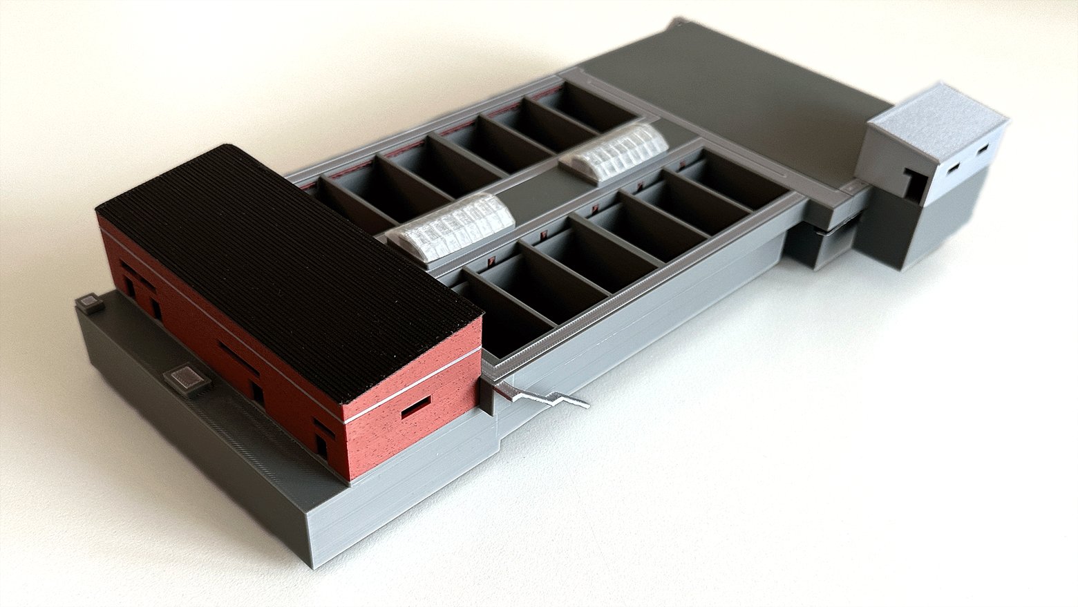
Presentation models print in sections so the roof and upper floors lift away, which is what makes them useful to a client rather than decorative
Small scale: architectural models and presentation pieces
The studio model is the oldest use of additive manufacturing in architecture and still the most common. It settles questions a screen cannot: how a mass reads in daylight, how a roof meets a wall, whether a plan stays legible from above. In Malaysia it also serves a practical purpose, because planning submissions and client sign-offs generally go more smoothly with something physical on the table.
FDM for mass, volume and structure
Fused deposition modelling is the default for architectural models. Desktop machines are inexpensive relative to what they produce, the material choice is wide, and build volumes suit a 1:100 or 1:200 model printed in a handful of pieces. Layer heights commonly run from about 0.1 mm to 0.3 mm, which is fine enough for wall thicknesses and openings once you have scaled the drawing sensibly.
The complication is part size. A long section base, a site block or a 1:50 sectional model will not fit a small build plate, so you either split the model and join it at floor levels, or you move up to a machine with a larger envelope. That is where the FDM 3D printer range splits into studio machines and large-format machines. A Bambu Lab printer handles everyday studio work and fast design iterations, CreatBot and Mingda cover the larger envelopes, and Intamsys suits practices printing engineering polymers that need a heated chamber rather than a draught-free corner of the office.
Resin printing for facade detail
Where a model has to show a perforated screen, a lattice, a balustrade or a fine window mullion, stereolithography and DLP printers beat FDM outright. Photopolymer layers are measured in tens of microns, so small features survive that would be lost between FDM extrusion lines. The trade-off is build volume, cost per part and handling: resin models are brittle, and clear resins yellow under ultraviolet light, which matters for anything that will sit on a shelf or travel to a client presentation. The SLA and DLP and MSLA pages set out the differences between the two.
Binder jetting for full-colour models
If the model has to communicate material, zoning, planting or a facade palette, binder jetting is the technology to look at. A powder bed of gypsum-based composite is bonded by a jetted binder, layer by layer, and the colour comes from the print head rather than from paint. You get a coloured model in one piece with no assembly and no painting, which is exactly what a competition board or a public consultation display needs.
The limits are real. Binder-jetted parts are more fragile than FDM and absorb moisture, so they need sealing or a careful coat of infiltrant before they are handled. They are also not the right tool for a structural or assemble-it-yourself study model, where toughness matters more than colour.
Model type
Technology
Typical material
Why it works
Massing model, 1:500 to 1:200
FDM
PLA
Light, quick to reprint when the scheme moves, forgiving of a coarse mesh
Detail model, 1:100 to 1:50
FDM with a fine nozzle
PLA, PETG
Thin walls and openings need a smaller nozzle and a lower layer height
Coloured presentation model
Binder jetting
Gypsum-based composite
Full colour in one piece, no assembly or painting
Facade screen or mullion detail
Resin, SLA or DLP
Photopolymer
Feature sizes that FDM cannot hold
Sectional or exploded model
FDM, printed as slices
PETG, ABS
Slices can be lifted apart so the interior can be read
Model that will be handled hard
FDM
PETG, ASA, TPU
Tough, UV-stable and able to take flexible parts where needed
Filament choice in a tropical climate
Material selection matters more in Malaysia than in a temperate market. PLA is dimensionally stable and prints cleanly, which suits a model that lives on a shelf. PETG adds toughness and a little heat resistance. ABS and ASA resist sunlight better but warp during printing unless the machine is enclosed. Nylon and other engineering polymers perform well once they are dry, and they absorb moisture from the air quickly, so filament drying and sealed storage are part of the process rather than an accessory to it. Specialist suppliers such as 3DXTech, whose filament Trinventor Solution stocks, publish drying profiles for each material; follow them, and store spools dry between jobs.
Medium scale: formwork, moulds and patterns
Move up in size and the argument for printing changes completely. Nobody prints a flat, repeated wall form, because timber and steel panels already do that job well and get reused. Printing wins where geometry is expensive to produce by hand: curves that do not repeat, deep relief, undercuts, internal channels and one-off features. This is the scale at which additive manufacturing most reliably pays for itself on a construction project.
Printed formwork for concrete
Concrete formwork does not have to be strong the way a structural element is strong. It has to be stiff enough to hold wet concrete for a short period, sealed enough that the paste does not bleed out, and accurate enough that the finished face matches the intent. That set of requirements is well within reach of large-format polymer printing, and it means the form can be a printed shell rather than a heavy fabricated panel.
Two approaches are common. In the first, the printed shell is stripped and can sometimes be reused for a small batch of identical casts. In the second, the shell is sacrificed: it becomes a permanent part of the element, sometimes acting as a facing layer or insulation, and stays in place after the pour. The sacrificial route is popular for columns and complex nodes, where removing a rigid mould would be awkward or impossible.
Large-format printers fed with pellets or with fibre-filled filament are the usual machines here, and recycled polymer is a sensible feedstock for a part with a short working life. If you need to compare what is available, the large-format and pellet machines on the site cover the range.
Mould masters and casting patterns
Most precast facade elements are not cast directly in a printed mould. A master pattern is printed, finished and sealed, a rubber mould is taken from it, and that rubber mould produces the repeat castings. One printed master therefore serves a whole elevation, which is where the cost per element collapses. The same logic applies to glass-fibre-reinforced concrete panels, terrazzo tiles and decorative cast stone.
Metal casting uses the same principle with a different machine. Binder jetting in sand builds a mould or core directly in a bed of sand, so no pattern has to exist at all. That opens up undercuts, hollows and internal channels that a two-part pattern cannot produce, and it is how complex structural connectors and fittings get cast without weeks of pattern work. Printing the pattern in a wax-like or burnout material is the alternative for investment casting, and metal powder bed machines such as those in the SLM range cover the case where no casting is wanted at all.
Application
Traditional route
Printed route
Where the advantage sits
Doubly curved wall or shell
Ply ribs, skilled carpentry, CNC foam, heavy waste
Print the form or a mould master in one piece
Printed wins on labour, waste and achievable curvature
Straight, repeated wall form
Standard timber or steel panels, reused many times
Printing is slower and the form is not reused the same way
Traditional wins; do not print flat formwork
Ornate precast panel
Hand-carved pattern, plaster, then silicone
Print the master, cast the rubber mould from it
Printed wins for one-offs and short runs
Cast structural node
Pattern making then foundry casting
Binder-jetted sand mould built directly from the model
Printed wins on lead time and on internal geometry
Jigs, templates and setting-out aids
Joinery shop and site measurement
Print from the coordinated model
Printed wins wherever the geometry is not rectangular
Large scale: printing walls and structures
Construction printing extrudes a cementitious mix from a nozzle and builds a wall by stacking beads. The mix has to do two things at once: flow through a pump and a hose without setting, then stand up under its own weight the moment it leaves the nozzle. That second property is what makes printed concrete a different material from cast concrete. Printable mixes carry fine aggregate rather than coarse stone, rely on admixtures to control open time and set, and often include fibres for crack control.
Gantry, robotic arm and mobile systems
A gantry printer spans the whole footprint on a frame. It is rigid, simple to control and well suited to a rectangular building where the machine can be set up once and left alone. A robotic arm works instead within a reachable envelope, so it suits columns, curved elements and jobs where the machine has to move around the site. Mobile and boom-mounted systems trade some accuracy for the ability to work across a large site without a fixed frame. Off-site printing is a fourth option: wall panels are printed in a factory, cured under cover with proper quality control, then transported and erected like precast units.
In all cases the scale is different from the studio. Bead widths and layer heights are measured in centimetres rather than fractions of a millimetre, the nozzle travels at metres per minute, and a house wall goes up in hours rather than days. On-site printing exposes the process to rain, wind and direct sun, which is a live consideration in a Malaysian monsoon pattern, so most projects protect the print area with a temporary canopy.
Reinforcement, joints and finishing
Printing places concrete; it does not place reinforcement. In practice, horizontal bars are positioned by hand as the wall rises, mesh is embedded between layers, or fibres in the mix carry the crack control. Vertical continuity is handled with starter bars cast into the foundation and later grouted or tied into a cast element. Where a printed wall meets a cast slab or column, engineers design and test the interface explicitly, because a cold joint between printed layers behaves differently from a monolithic pour.
Surface finish follows from the process. Layer lines are visible and intentional in some designs, unwanted in others, so printed walls are typically rendered, plastered, tiled or clad. You cannot hold a millimetre tolerance on an extruded bead; the achievable tolerance on a printed wall is measured in centimetres, and the design has to allow for that from the start.
Approvals and what gets built today
Printed structural concrete does not yet have a mature design code in Malaysia. Approval therefore rests on a qualified engineer’s design, documented mix testing, and early agreement with the local authority rather than on a clause in a standard. That shapes what is realistically built now: single-storey walls, columns, boundary walls, benches, planters, bus stops and other site elements where the geometry is awkward, the loading is modest, or the repetition makes printing worthwhile. Multi-storey printed construction exists as pilot work in the region, and it is engineering-led rather than a standard offering.
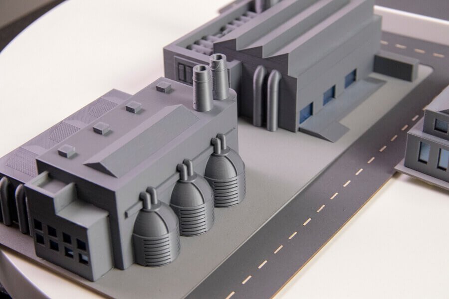
Technical and plant models read as engineering documents: tanks, pipework and site layout are modelled to scale so they can be measured against the plan
Scale versus technology versus typical output
Scale
Typical technology
Machine format
Materials
Typical output
Tolerance and finish
Small, 1:500 to 1:200
FDM
Desktop, single nozzle
PLA
Massing models, site blocks, zoning studies
Tenths of a millimetre; curves faceted if the mesh is coarse
Small, 1:100 to 1:50
FDM with a fine nozzle
Desktop, enclosed
PLA, PETG, ASA
Detail models, facade fragments, sections
Sub-millimetre; layer lines visible unless filled and primed
Small, presentation
Binder jetting
Powder bed, full colour
Gypsum-based composite
Coloured presentation and consultation models
Fine detail, matt surface, low toughness, needs sealing
Medium, moulds
Resin and FDM
Desktop to mid-format
Photopolymer, PLA, PETG
Mould masters, casting patterns, jigs
Sub-millimetre on the master; casting sets the final tolerance
Medium, formwork
Large-format FDM and pellet extrusion
Gantry or large frame
Fibre-filled and recycled polymer
Formwork for curved concrete, GFRC moulds
A few millimetres; bead lines sanded or sealed before the pour
Medium, casting
Binder jetting in sand
Powder bed with sand
Silica sand and binder
Moulds and cores for cast metal nodes
Determined by the casting process, not the printer
Large, structure
Concrete extrusion
Gantry, robotic arm or mobile rig
Cementitious mix with admixtures and fibres
Walls, columns, benches, small buildings
Centimetres; surface finished after printing
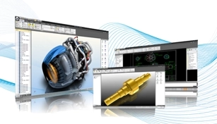
The BIM model stays the single source of truth; the printed piece is one output from it, sitting beside the CAD it came from
BIM is the data source, not the deliverable
A BIM model carries intelligence: walls with types and materials, slabs with thickness and levels, spaces, schedules, and the coordination between structure, services and envelope. A printer understands none of that. It consumes a mesh and a set of toolpaths. The printable file is therefore a derived, simplified artefact, and the BIM model stays the source of truth behind it.
That distinction matters more as the print gets bigger. A clash caught in the model costs a designer an afternoon. The same clash discovered once the wall is half printed costs a day of site work and a rejected element. For anything at formwork scale or above, the model has to be coordinated before it is converted, not after.
BIM also does the accounting. Once the geometry is modelled, material volume, print time and the comparison against a traditional option fall out of the same data, so the decision between printing a form and building it by hand is made on quantities rather than on instinct. Adding sequencing to the model gives a fourth dimension: the order in which elements are printed or erected becomes explicit, which is exactly the information a site team needs.
From a BIM model to a printable file
Define the print scope. Decide what is actually being printed. A whole building is rarely one print; a wall panel, a column, a node or a model storey usually is.
Strip what the machine cannot use. Hide fittings, finishes, insulation, rebates, annotations, hatches and reference planes. Export the geometry you need, not the file.
Reduce to a watertight solid. Union overlapping elements, close gaps at junctions and delete the internal faces left behind by joined objects. Most stalled projects stall here, because an architectural model is built from touching objects rather than from one continuous solid.
Convert to a mesh or a solid. STL and 3MF are the common mesh carriers, and STEP suits CAM work where a solid is preferred. If the exchange goes through an open BIM format, expect to convert the geometry into a mesh afterwards.
Set the tessellation deliberately. A coarse chord and angle tolerance gives faceted cylinders and a small file. A fine tolerance gives smooth curves and a file nothing will open. Choose the coarsest setting that still reads correctly at the scale of the print.
Check and repair. The mesh must be watertight, with consistent normals, no self-intersections and no walls thinner than the process can build. Meshing and repair tools such as Geomagic and inspection software handle this step and also verify the printed part against the model afterwards.
Slice and orient. Choose wall count, infill, layer height and supports, and place seams where they will not show. At model scale the driver is surface appearance. At construction scale it is bead geometry against set time and buildability.
Scale, then re-check. A scale factor changes every wall thickness at once, and thin elements can disappear below the printable minimum.
Tolerances and scale factors
Scale is a design decision, not a division. Take a 100 mm wall at 1:100: it becomes 1 mm, which a 0.4 mm nozzle can only produce as two or three extrusion lines, and any thinner element vanishes altogether. Good model practice is therefore to exaggerate selectively, thickening walls, fattening columns and deepening reveals so the model reads correctly, then noting the exaggeration on the drawing so nobody measures it.
The same logic runs through every printed part. A well-maintained FDM machine holds dimensions to a few tenths of a millimetre. At 1:100 that is a matter of tens of millimetres on site, which is fine for a massing study and useless as a tolerance check. Resin printers do better on feature size but shrink slightly during curing, so panel-like parts tend to bow. ABS and ASA move more than PLA during printing, which is why large flat parts need an enclosed chamber, a brim and patience. At construction scale the tolerance is centimetres, and the whole detail set has to be written around that number rather than against it.
Where it saves time and money
The honest summary is that printing wins on geometry and loses on repetition. Any task where the same simple shape is produced many times belongs to conventional methods. Any task where a skilled person has to make a complicated shape once, or slightly differently each time, belongs to printing.
Design iteration. Laser-cut and hand-built models are rebuilt from scratch at each major change. A printed model is re-sliced and reprinted, and only the parts that moved have to be redone.
Curved formwork. The labour and material waste in conventional curved formwork is what printed formwork displaces, not the cost of the concrete.
Mould masters. One printed master feeding a rubber mould serves an entire elevation of identical panels.
Cast connections. A binder-jetted sand mould removes pattern making from the programme, which is often the longest lead item on a bespoke connection.
Site elements. Benches, planters, bollards and small structures that would otherwise be precast and transported can be printed close to where they are installed.
Not on the list. Flat walls, standard blockwork and repeated steel formwork. Printing those is slower, needs more supervision and is harder to approve.
Realistic limits
Printed parts are directional. FDM parts are weaker across the layer boundaries than along them, so the orientation of a part on the bed is an engineering decision, not a convenience. Printed concrete behaves in a similar way where the bead direction and the layer interfaces govern.
Modelling is the bottleneck. A printer is the easy purchase. Turning a coordination model into a watertight printable solid takes a person who knows both meshes and construction, and that skill is the scarce resource.
Print time governs everything. A large model can run for days, and a failure near the end of that run has to be recovered, restarted or designed around with a split part. Long prints need supervision, spare material and a plan B.
Build volume decides the assembly. If the element does not fit, it becomes a jointed assembly, and joints have to be designed so they can be printed, aligned and finished.
Finish is a separate cost. Sanding, filling, priming, sealing and rendering are all real activities with real time attached. Budget them into the comparison.
Reinforcement remains manual at construction scale. Until placement and continuity are solved by the process itself, printed concrete will stay in the territory where reinforcement demand is low or where bars can be placed between layers and verified on site.
Approval still needs an engineer. There is no shortcut around a design submission, mix testing and a qualified sign-off for anything load-bearing.
Humidity is a material problem. In a tropical climate, filament, gypsum-based powder and cementitious mixes all react to moisture. Storage and drying are part of the workflow, not optional housekeeping.
What makes sense on a Malaysian bench
For a practice starting out, the sequence that works is small first. A desktop enclosed FDM machine covers massing, sections and facade studies, and it teaches the studio how to prepare models for a printer, which is the skill that carries through every scale. Add a resin printer for detail work and for facade screens. Add a scanner when the work involves existing buildings, because a handheld or tripod-mounted scanner, such as the units in the multi-functional 3D scanner range, turns an as-built survey into a point cloud, then into a model, then into a printable file. Take advice from a reverse engineering workflow before you buy, since the scan-to-print chain is where renovating practices get stuck.
Large-format printing is usually the second or third step, and many practices never need to own it. Formwork and mould work can be bought in from a service provider until the volume justifies a machine, which is how most first large-format purchases are timed. A CAD and mesh toolchain matters at least as much as the hardware: a modelling package such as those under CAD software in Malaysia, a mesh repair tool, and a slicer you actually understand.
Frequently asked questions
Can a printer replace a physical model shop?
For massing, sections and repetitive facade studies it largely does, because the geometry is generated from the model the practice already has. For large-scale contextual models, hand finishing, landscaping and lighting effects, a model shop still adds value. Most practices run both and send the printer the parts where accuracy and repetition matter.
Which scale should a Malaysian practice buy first?
Small scale. A desktop enclosed FDM printer gives the fastest return because it feeds design reviews and presentations directly, and it builds the modelling and file preparation skills that later scales depend on. Large-format and construction-scale work is better bought as a service until the volume is there.
Can printed concrete be used for a load-bearing wall?
Yes, in principle, and it has been done in pilot projects. In practice the design has to be signed off by an engineer, the mix has to be tested and documented, the reinforcement strategy has to be resolved, and the local authority has to accept the submission on that basis rather than on an established code clause.
How accurate is a printed architectural model?
A well-set-up FDM printer holds a few tenths of a millimetre, which is more than enough for massing and presentation. That is not the same as a scale-accurate survey: thin walls, columns and openings are deliberately exaggerated so the model reads correctly, so a printed model should never be measured as though it were a drawing.
Does the BIM model have to be rebuilt for printing?
No. It has to be prepared. The relevant geometry is isolated, reduced to watertight solids, converted to a mesh with a deliberate tessellation setting, repaired, then sliced. The BIM model itself stays as it is, and the printable file is a derived export that can be regenerated whenever the design changes.