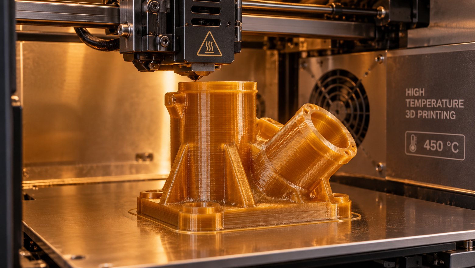
Thermoplastic Polyimide 3D Printing: High-Temp Parts
Thermoplastic Polyimide 3D Printing: High-Temperature Performance
Quick verdict: Thermoplastic polyimide is the filament you specify when a printed part must hold its shape at 200 °C and above, resist fuels and solvents, and stay dimensionally stable while it does it. It demands an all-metal hotend running above 400 °C, a heated chamber and a slow, deliberate print. If your parts never pass 120 °C, a cheaper high-temperature polymer will do the same job.
Only a handful of engineering polymers can be 3D printed, and far fewer keep working once the temperature climbs past the boiling point of water. Thermoplastic polyimide sits at the top of that short list: it is the material engineers reach for when metal is too heavy and every other plastic softens too early.
This guide covers what it is, where its real temperature ceiling sits, how it compares with PEEK, PEKK and ULTEM, what the machine must do, and the settings and fixes that separate a usable part from an expensive failure.
What thermoplastic polyimide is
Polyimide is a family of polymers built around imide rings in the backbone of the chain. Those rings make the chain stiff and thermally stable, which is why polyimides have been used for decades in laminates, films and coatings for electrical and aerospace work. Most classic polyimides are thermosetting: once formed, they cannot be melted again.
Thermoplastic polyimide, usually shortened to TPI and often written simply as PI on a data sheet, is the melt-processable branch of the family. It can be pushed through an extruder, drawn into filament, melted in a printer and melted again. That single property is what makes it a 3D printing material at all.
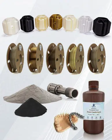
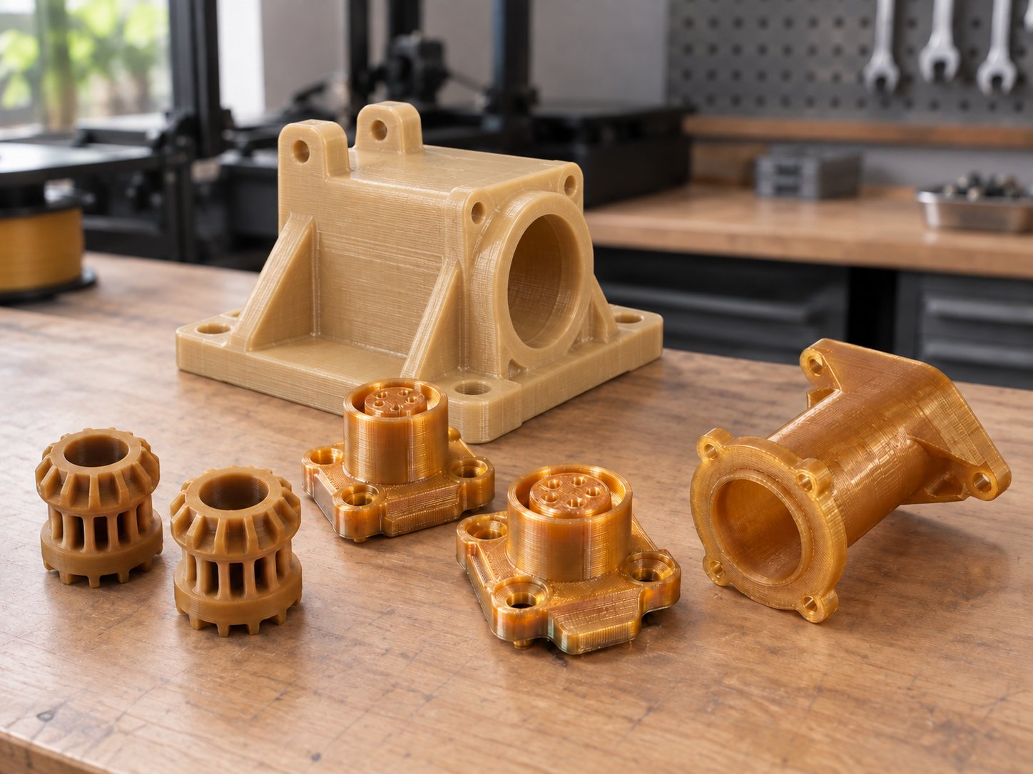
It arrives as filament in standard diameters, unfilled or with fillers such as carbon fibre, glass fibre or graphite for extra stiffness and wear resistance. In industry it appears as connectors, bushings and bearings, seals, wafer handling components, ducting, and parts that live inside ovens, autoclaves and engine bays.
Why an amorphous polymer prints differently from PEEK
TPI is amorphous. Its chains stay disordered rather than folding into crystalline lamellae, so the material takes its stiffness from the rigidity of the backbone. That one fact changes the printing behaviour more than any other property.
A semi-crystalline polymer such as PEEK or PEKK only develops its full strength if it crystallises as it cools, and crystallisation is fussy. It wants the chamber held inside a narrow band, and the crystals that form pull the part inwards unevenly. Amorphous TPI has no crystallisation step to get wrong. Shrinkage is low and roughly even in every direction, and layers bond by chain diffusion rather than being interrupted by crystal nucleation. Large flat parts stay flat, and the Z direction is far less of a weak point.
The trade-off sits at the top of the range. Crystals give a semi-crystalline polymer a second line of defence, so PEEK keeps useful stiffness above its own glass transition. Amorphous TPI has only the glass transition. Above it the part does not melt, but it softens and creeps under load. Because that transition sits very high, TPI still wins on usable temperature, though the margin above it is thinner than the headline numbers suggest.
The temperature ceiling: what TPI survives in service
Temperature resistance is not one number, and treating it as one is how parts fail in the field. Four figures matter, and they are measured differently:
Glass transition temperature: where the amorphous chains start to move. Typical grades sit in the region of 240 to 260 °C, and this is the most important number for a printed part.
Continuous service temperature: the highest temperature a part can sit at for thousands of hours under a reasonable load and still be trusted. For TPI it is commonly quoted in the 200 to 230 °C band.
Short-term excursion: a brief spike the part survives without deforming permanently. Useful for a soldering process or a cleaning cycle, useless as a design limit.
Heat deflection temperature: measured under load, and always lower than the glass transition. It describes a part carrying something, not one merely sitting there.
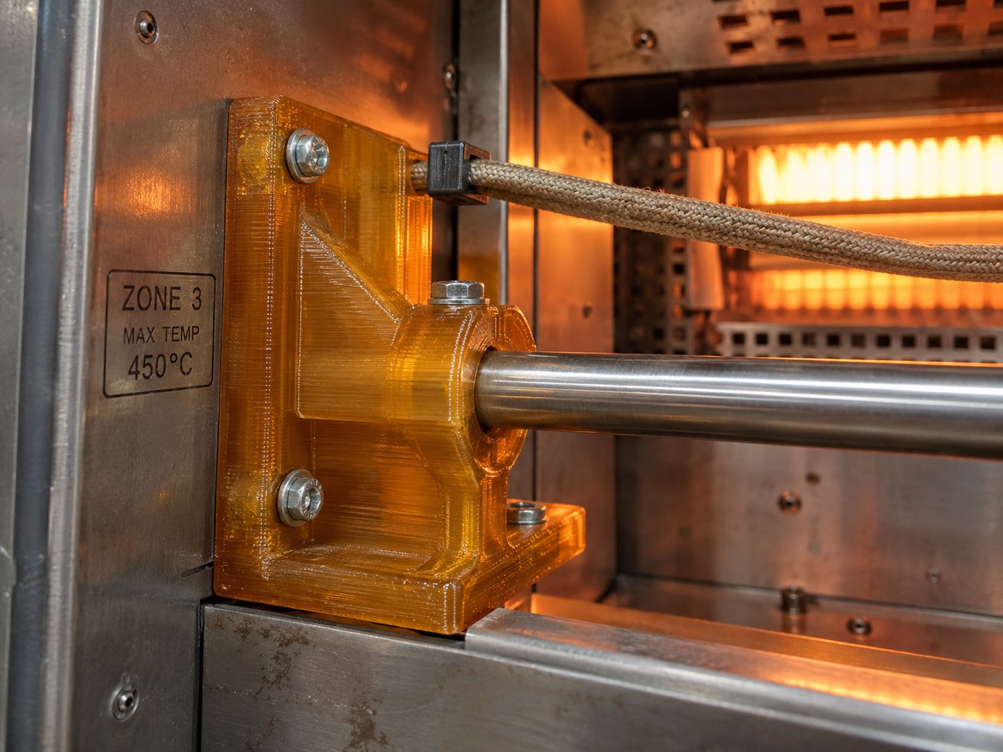
The practical question is narrower. Can the part go through autoclave cycles at hospital sterilisation temperatures without going soft? Can it sit beside a reflow oven or inside a process tool? A printed TPI part handles those conditions where a cheaper polymer would sag. It will not carry a heavy sustained load at the very top of its range.
Dimensional stability and creep resistance
Thermoplastic polyimide has a low coefficient of thermal expansion for a printable polymer, low enough that a part can be mated to a metal component without the fit drifting open when the assembly gets hot. The amorphous structure helps: there is no crystalline phase to change volume as it cools.
Moisture is the other half of stability, and it matters in a humid climate. Nylon and some other engineering filaments absorb water from the air and grow as they do. TPI takes on very little, so a part measured on the day it was printed is still that size next month.
Creep is the limit to plan around. An amorphous polymer held under constant load, close to its glass transition, deforms gradually even though it never melts. Design thicker walls, spread the load over a larger area, and avoid leaving a printed TPI part permanently compressed or bent in service. A controlled heat soak below the glass transition after printing relaxes locked-in stresses and reduces how much a part moves the first time it is heated in use.
Chemical resistance: what attacks it and what does not
This is where thermoplastic polyimide earns its place in oil and gas, semiconductor and transport work. It resists hydrocarbons, fuels, oils and hydraulic fluids, along with alcohols, ketones, weak acids and most solvents. It also has very low outgassing, which matters for vacuum chambers and sealed electronics, and it is inherently flame resistant rather than relying on an additive.
It is not indestructible. Strong bases such as sodium hydroxide attack it, as do hot concentrated acids. Chlorinated solvents will damage it, and amines are a known weak point for polyimides generally. Filled grades behave differently from unfilled ones, and every resistance figure is quoted for a specific concentration, temperature and exposure time, so have your exact combination tested rather than trusting a general table.
Polyimide vs PEEK, PEKK and ULTEM
These four are often quoted against each other, and they are not interchangeable. Two are amorphous and two are semi-crystalline, and that distinction drives almost every practical difference.
Material
Structure
Glass transition
Continuous use
Chamber needed
Strengths
Watch out for
Thermoplastic polyimide (TPI)
Amorphous
Around 240 to 260 °C
Up to about 230 °C
150 to 200 °C
Highest usable temperature, minimal warping, strong chemical resistance, low outgassing
Highest material cost, needs a true high-temperature machine, notch sensitive
PEEK
Semi-crystalline
Around 143 °C
Up to about 250 °C
120 to 160 °C
Excellent chemical and wear resistance, tough, well established
Properties depend on crystallinity, so it warps and needs chamber control
PEKK
Semi-crystalline
Around 160 °C
Roughly 200 to 250 °C
120 to 180 °C
PEEK-family performance with easier processing and better bonding
Still needs a hot chamber, less widely stocked than PEEK
PEI (ULTEM)
Amorphous
Around 217 °C
Roughly 150 to 170 °C
130 to 180 °C
Stiff, flame resistant, low warp, good electricals
Lower ceiling than polyimide, brittle under impact
Read the table by application rather than by ranking. If a part must survive 200 °C or more with a load on it, polyimide or PEEK are the serious options. For stiffness and electrical performance up to around 150 °C, PEI does the job with far less machine pressure, while PEKK sits between PEEK and polyimide as a compromise on processing difficulty. Where more rigidity is needed at that ceiling, a carbon-fibre grade such as CARBONX ULTEM PEI+CF adds stiffness, at the cost of some impact resistance. Where chemical exposure is the dominant risk rather than heat, the semi-crystalline materials are often the better first choice.
Where the cost is justified
Thermoplastic polyimide is the most expensive of these filaments, typically at or above PEEK depending on grade and filler, and a failed print wastes material you cannot recover. Two costs sit behind the reel price: the machine must be a genuine high-temperature platform, and a print that runs for many hours occupies that machine throughout.
It pays for itself in a recognisable set of situations:
The part replaces a machined metal component, the quantity is low, and tooling would take weeks to arrange.
The part is a jig, fixture or tray that passes through an oven, autoclave or soldering process, where a softer polymer would distort and scrap the product it holds.
The part lives inside a machine or vehicle where failure means downtime, and the material is a small share of what that downtime costs.
The geometry is complex enough that machining would need several setups, or would not be possible at all.
It is the wrong choice for prototypes, cosmetic parts, anything that stays below roughly 120 °C, and large simple shapes where a cheaper high-temperature polymer already passes the test. Buying TPI for those jobs spends money on headroom you will never use.
Machine requirements: hotend, bed and chamber
You cannot print thermoplastic polyimide on a standard desktop FDM printer, and no firmware tweak will change that. The machine has to be built for it.
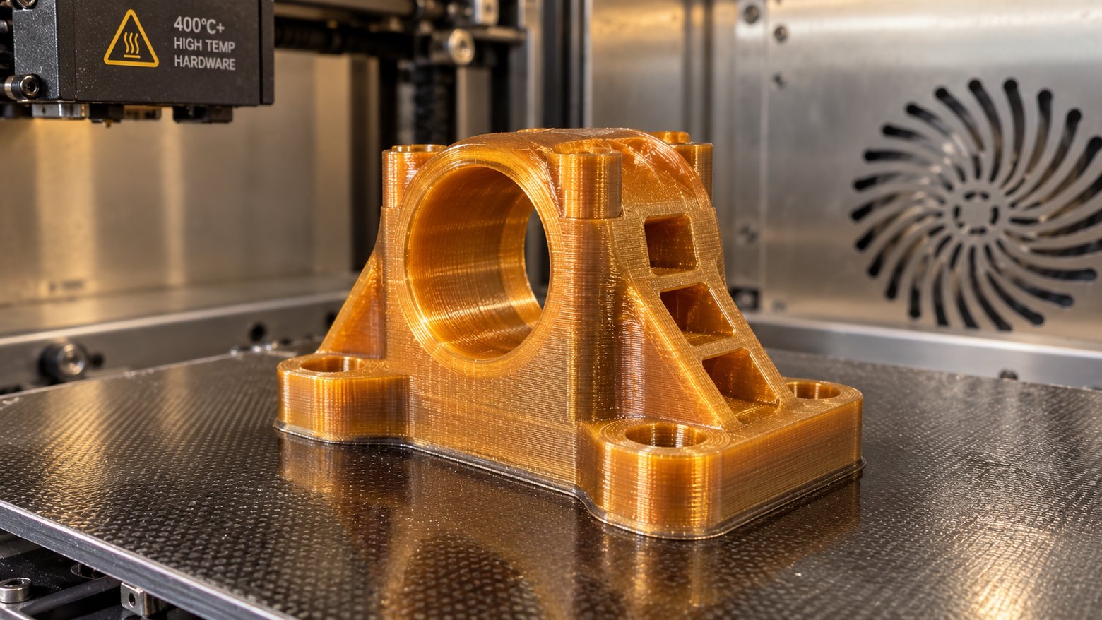
All-metal hotend rated for the temperature. The melt zone must reach 380 to 420 °C reliably, which rules out any hotend with a polytetrafluoroethylene liner. Use a thermocouple or high-temperature thermistor: accuracy at 400 °C is a different problem to accuracy at 240 °C.
Hardened or wear-resistant nozzle. Unfilled polyimide is not abrasive, but carbon fibre and glass fibre grades open up a brass nozzle quickly.
Heated bed at 140 to 180 °C. For adhesion, and to narrow the gap between the first layer and the rest of the part.
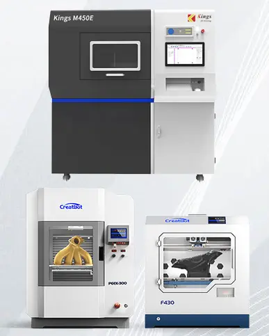
Actively heated chamber at 150 to 200 °C. This decides whether a machine can print TPI at all. Most enclosed desktop printers hold a chamber around 60 to 70 °C, nowhere near enough.
Chamber-rated components. Motors, belts, bearings, wiring and the mainboard either sit inside that heat or are protected from it, which is why high-temperature FDM platforms are a separate class of machine.
Drying and storage. Polyimide absorbs little moisture compared with nylon, but printing it wet causes popping, voids and weak layers. Dry it above the temperature a consumer dryer can reach, then keep it sealed with desiccant.
Ventilation and filtration. Printing above 400 °C releases ultrafine particles and volatile organic compounds, so enclosures are filtered and extracted as standard practice.
Print settings that work
These are starting points, not a recipe. Run a small test part first and adjust from there.
Setting
Starting point
Why
Nozzle temperature
380 to 420 °C
Very viscous melt; the upper end bonds layers better
Bed temperature
140 to 180 °C
Adhesion and a smaller thermal gap at the base
Chamber temperature
150 to 200 °C
The dominant setting; a cold chamber means warping
Nozzle diameter
0.4 to 0.6 mm
A thick melt flows better through a larger orifice
Layer height
0.15 to 0.25 mm
Thicker layers bond reliably at high viscosity
Print speed
15 to 40 mm/s
Slow; excess flow causes under-extrusion
Part cooling fan
Off
Directed cooling encourages warping and delamination
Retraction
Short and slow, or none
The hot chamber keeps the polymer fluid
First layer
0.2 to 0.3 mm, slow
Holds the part down for the hours that follow
Common problems and fixes
Problem
Likely cause
What to do
Corners lift or the part warps
Chamber too cool, fan running, part too large for the gradient
Raise chamber temperature, switch the fan off, add a brim, slow the first layers
Layers separate or the part splits along Z
Nozzle temperature too low, speed too high, layer too thin
Reduce speed or layer height, increase nozzle diameter, check for a partial blockage
Discolouration or a burnt smell
Polymer sitting in the hotend too long at 400 °C
Purge between prints, avoid long pauses with the nozzle hot
Electronics failing during a print
Components inside the chamber are not rated for the heat
Use a platform designed for a heated chamber, not a modified desktop printer
Frequently asked questions
What temperature can 3D printed polyimide withstand?
Continuous service in the region of 200 to 230 °C is the working figure for typical grades, with a glass transition around 240 to 260 °C. Short excursions above that are survivable, but a part under load at the top of the range will soften and creep.
Is polyimide better than PEEK?
For sustained heat, polyimide has the higher ceiling and warps far less, because it is amorphous and has no crystallinity to control. PEEK is tougher in some respects and better established in medical and aerospace work. Choose on the dominant requirement.
Can I print polyimide on a standard 3D printer?
No. It needs an all-metal hotend running at 380 to 420 °C and a chamber at 150 to 200 °C. A typical enclosed desktop printer holds its chamber near 60 to 70 °C and its hotend is not rated for the melt temperature, so the print will warp apart or fail to extrude.
Does thermoplastic polyimide need annealing?
Not for crystallinity, because there is no crystalline phase to develop. A controlled heat soak below the glass transition is still worth doing on parts that must hold tight tolerances, because it relaxes the stresses locked in during printing.
Is polyimide filament safe to print indoors?
Printing above 400 °C produces ultrafine particles and volatile organic compounds, so it belongs in an enclosure with filtration and, ideally, a route to extract air outside the workspace. Keep the machine away from where people are working.