Where 3D scanning fits in machinery and fabrication
The expensive part of machinery work is rarely the metal. It is the information — a drawing that never existed, a part from a machine with no local agent, a worn component whose original profile has to be re-established before anything can be made. Scanning answers that by turning the physical part into geometry you can work with.
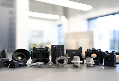
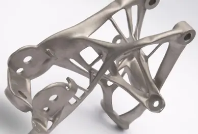
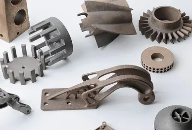
In practice it breaks into three jobs. Reverse engineering: scan an existing component, convert it to CAD, then manufacture a replacement or a revision of it. Inspection: prove that a machined or cast part matches its design, without sending it away. Reconstruction: capture worn or damaged geometry — shafts, gears, impellers, housings, wear plates — so the repair can be modelled rather than guessed.
What we would use, and why
| What you need to do | What we would use | Why that one |
|---|
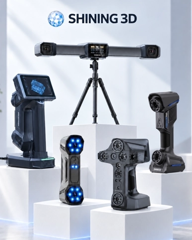
| Reverse engineer an obsolete or imported part | FreeScan Combo+ Wireless with scan-to-CAD | Metrology-grade handheld, 0.02 mm, wireless, with a single-line deep-pocket mode for internal features and bores — no spray on machined surfaces |
| Inspect machined parts against CAD, on the shop floor | FreeScan Omni | Scanning, inspection and reporting all on the scanner — no PC beside the machine, which is what makes shop-floor checking practical |
| Measure large castings, frames or machine beds accurately | FreeScan Combo+ Wireless with VPG | Built-in video photogrammetry stops error accumulating over metres; where the same large assembly is measured repeatedly, a tracked system removes operator variation |
| Measure small precision components in volume | AutoScan Inspec2 or OptimScan Q12 | The desktop system automates the cycle at 0.01 mm class; the Q12 reaches 0.005 mm where the tolerance demands it |
| Handle a one-off breakdown with no equipment on site | Our 3D scanning service | Quoted per project — often the difference between a machine running next week and a machine waiting for a part |
Where drawings no longer exist, reverse engineering is the route back to manufacturable data: mesh for reference, then STEP or IGES once the geometry has been rebuilt. Inspection output is a deviation report against CAD — colour map, dimensions, GD&T. Details on what a project delivers, and the sector picture on 3D scanning by industry.
Practical notes
The deciding questions are the same on every job: how tight is the tolerance, how big is the part, and does it have to be measured once or repeatedly. A part that fits in the hand and is measured in production belongs on a desktop machine; a large casting measured once for a drawing belongs with a handheld; the same large assembly measured every month belongs with a tracked system.
We will also say when scanning is not the answer. If a competent drawing exists and the part is simple, measuring it directly is faster and cheaper.
Frequently asked questions
Can you reverse engineer a part with no drawings?
Yes — that is the standard case. The part is scanned, the geometry is rebuilt in CAD, and the output is a manufacturable model. Complex internal features, threads and bores are where the scanning mode matters most.
How accurate is scanned data for machined parts?
Metrology handhelds measure to 0.02 mm with volumetric accuracy of 0.02 + 0.03 mm/m, and desktop systems reach 0.01 mm class or finer. Tell us the tolerance you have to hold and we will say which system can prove it.
Can you scan a part that is still on the machine?
Handheld systems are often used exactly that way, on site rather than in a measuring room, provided the area is safe and there is access to the surfaces that matter.
What do we receive?
Mesh files (STL, OBJ, PLY), CAD-ready STEP or IGES after reverse engineering, and measured dimensions or a full deviation report if the job is inspection.
We only have one damaged part — is that enough?
Usually. Worn or broken geometry can be captured as scanned and then repaired or reconstructed in CAD, which is often faster than re-drawing the part from first principles.
What does machinery scanning cost in Malaysia?
Service work is quoted per project and equipment per configuration. Tell us the part, the tolerance and the deadline, and we will quote against those.